Experiences.
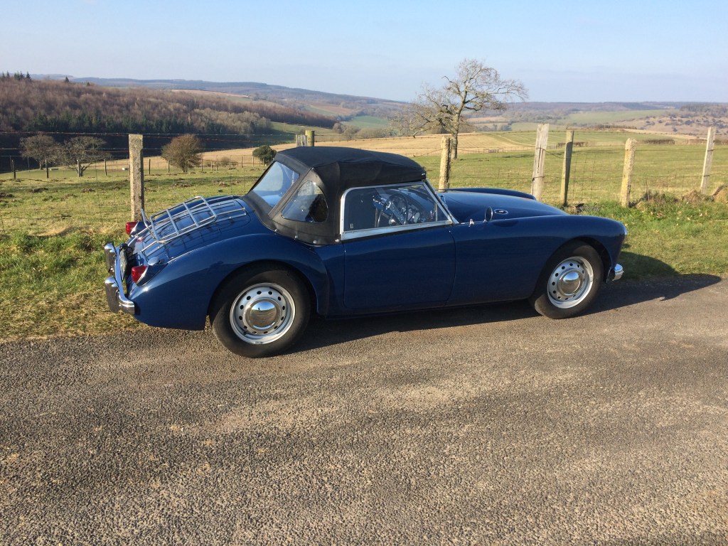
Maggie returned to the road in 2017 and to current date (2022) has covered 4800 miles. I’ve been fortunate in my working life to have driven some great cars, but I can genuinely say, that few have been as enjoyable as my humble MGA. The car performs more than adequately, handles superbly, feels way more modern than it should do and seems to bring joy wherever it goes.
There have been a few issues along the way, but nothing serious and all fairly normal for a classic car.
Electronic Ignition
The only failure was the Accuspark electronic ignition module, which failed once and was replaced, only to fail again. I reverted to the original points and condenser set up, which works perfectly well, is easy to time and can be easily replaced if needed. Update 2025 – Failure of the modules I discovered were due to my failing to correctly wire the coil to distributor/coil to power terminals, so not Accuspark’s fault! I’ve subsequently, this year fitted a new distributor with electronic module and matched coil which has been great.
Speedometer Cable
The speedo cable from the type 9 5-speed gearbox failed after about 2000 miles, which may have been due to routing. I chose to follow the Hi-gear route, which takes the long cable out through the transmission tunnel, curling across the floor and out through the toe-board, then arcing up through the engine bay, through the bulkhead into the speedo. It’s quite a tortuous route. The alternative is to find a 90 degree drive to fit the gearbox speedo drive gear, which enables a shorter cable and much more direct route. The second cable has completed another 2000 miles, so we’ll see how long it lasts.
Shock Absorber
The off-side front shock absorber started leaking from the start, but it took a while to establish that oil was coming from it. Like all BMC 1500 engines, a small leak from the rear main is pretty much standard, so it was difficult to differentiate between that and the damper, as a leak from the damper runs onto the chassis cross member and mingles with errant sump oil. Despite the dampers being reconditioned items, as they were fitted at the start of the restoration, any warranty had long expired. As it happened, on investigation, one of the original dampers was found to be good and was refitted after a thorough clean and fresh oil. It pleases me to think that one of the original dampers, certainly 50 years old, is still giving good service.
Wheel Shimmy
Once the car was on the road, it had a significant front wheel shimmy felt through the steering at speeds in excess of 65. The front wheels were balanced several times in an attempt to cure the problem, but to no effect. Eventually someone suggested checking the brake drums and I immediately remembered that I’d fitted new pattern drums to the front and 60 year old originals to the rear.
I swapped the drums, fitting the originals to the front. On road testing, the shimmy had disappeared completely, which was a real joy. I’m now planning on having the rear (new) drums balanced, as there will be some vibration through the rear axle.
Jan 2020
The drums were checked on a balancer and although the machined braking surface was true, the outer casting ran like a buckled wheel due to the poor rough casting process. The only option was to have them machined on the outside to shave off the high spots.
I’m fortunate to have nearby one of the last old machine shops in my area, run by two old school engineers that have the size of lathe to do a job like this. They ran the drums up on a lathe and confirmed just how far out of true they were. They carefully and lightly machined the outer surface of the drums until they ran true.
I refitted the drums and the car felt smoother and the braking was without any vibrations.


September 2020.
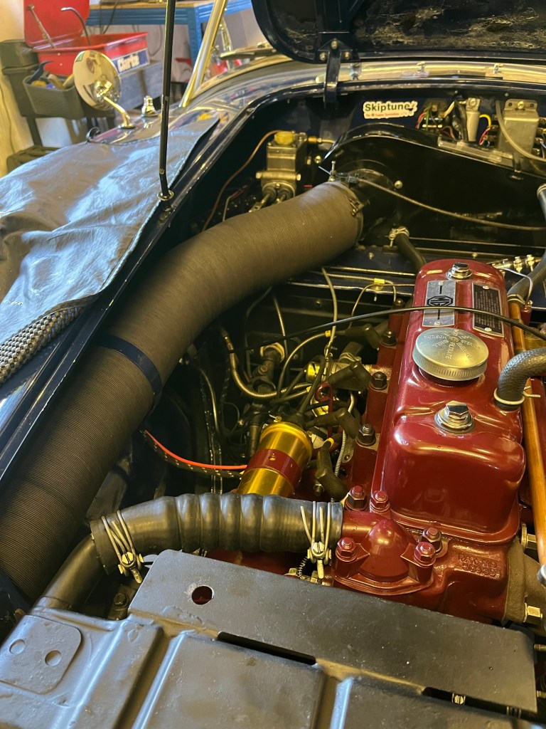
Engine Bay Fumes
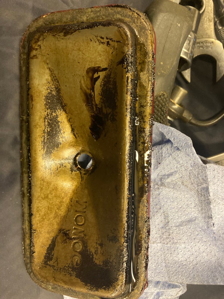
For some time now I’ve been aware of fumes from the engine bay, nothing serious, but noticeable on a good drive. A while ago, I checked all the possible bulkhead gaps and cable holes, replacing grommets and sealing everything else, so I’m happy that all’s tight there. So, l decided to properly pin down the source(s) of the fumes, which seemed to be both fuel and hot oil related. Looking down onto the engine bay from above, everything looked fine, dry and clean, so car up on ramps for a good look from underneath. Aside from the standard small drip from the rear seal which doesn’t cause fumes, l could see that there were signs of a small fuel weep from the float bowl bolt on the rear carb, which handily is nicely positioned above the exhaust! So that’s the fuel smell. Next I could see from below that both tappet cover plates were weeping slightly and one more than the other and as the oil runs down the block it builds up on the crankcase to sump flange close to the heat of the exhaust manifold. That should be the hot oil fumes then. To get to the tappet plates requires removal of the carbs and inlet manifold and releasing the exhaust manifold. All straightforward. On removal of the side plates, it was obvious where the oil was leaking as the lower gasket face was wet with it. Stopping oil leaks from the tappet covers is a challenge and judging by the amount of stuff on forums about it, an issue that troubles many B series engined classics. As there’s a temptation to over tighten the single retaining bolts, there’s a strong chance that the covers can be distorted, so the first thing to do is to check the mating faces with a straight edge. If ok and both faces of plate and block are clean, then new gaskets need to be stuck to the plate face with a suitable gasket paste, allowed to set, before carefully replacing. Care has to be taken not to over tighten, but the recommended 5 or 6 lbs torque seems too light. Also, there are three different types of gasket available in the Moss parts list alone – standard thin cork original, a thicker 6mm cork and a fabulously expensive silicone version (£18.90).personally, I think the original, carefully fitted is the one, as long as it’s the right size in the first place and not shrunk through age and storage. If that’s the case, when offered up to the cover face the gasket seems too small, then give it a soak in water and it should resume its correct size and shape. With the carbs off and on the bench, it was clear to see that there was a leak from the rubber seals at the base of the fuel bowl. I tried tightening the bolt, but it was fully tightened, so I replaced the rubber seals with new and the problem was solved. I’m waiting on the new gaskets before I can put it back together and see whether the fumes issue has been resolved. Job done and no fumes.

Oil Pressure
Since my engine rebuild, I’ve covered 4000 miles, without problems, but the oil pressure has always been just ok – 60/65lbs normal running and drop to 10/15lbs hot idling. This is within the bounds of the original BMC recommendation, but for a fully rebuilt engine, not so good. My thinking was that it could be the fact that I refitted the original oil pump, having checked the vane clearances and satisfied myself that it was good enough. The choice of living with it as it was, or major surgery was an easy one…..live with it! But last week I was ordering some parts for a spare engine rebuild and needed a new oil pressure relief valve kit (valve poppet, spring and cap) and noticed the additional shim washers along with the advice on adding them to increase oil pressure. Anyway, not being able to wait for delivery, I decided to have a go at fitting shims to my running engine. Access to the relief valve is relatively easy and with a bit of a fiddle I removed the cap and assembly. Firstly I checked the length of the relief spring, which should be three inches…..mine was 1/8th inch short. I found some 1/4inch flat washers and fitted two of them inside the valve, inserted a spare, correct length spring and refitted the assemblage to the block. On start up, the effect was immediate – 75lbs rising to 85 when revving hard. Idling hot is now 30/35, so a great result. I might try removing one shim to drop the max pressure to 75, but I was pretty chuffed. Easy job and cost nothing. Bill.
October 2020
Speedometer Failure
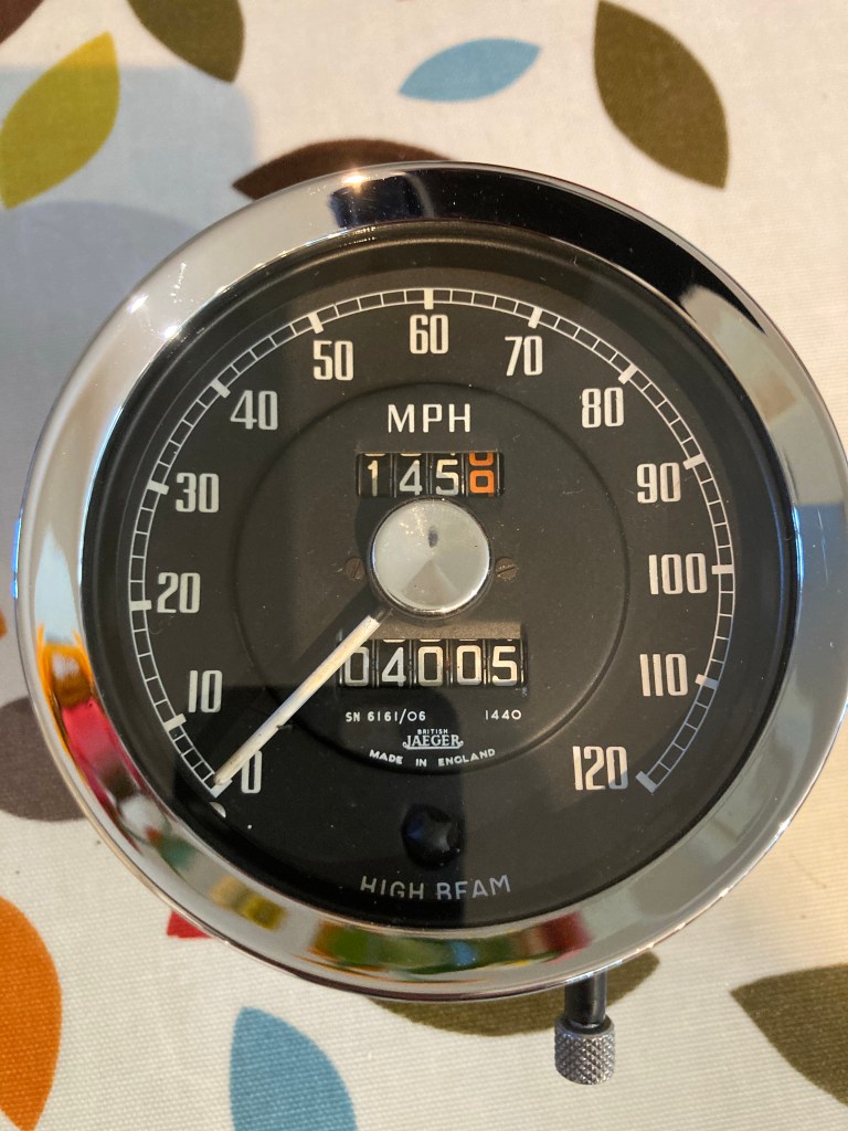
On recent runs, at speeds over 60 mph, the speedometer started to randomly and suddenly flick right around the scale and back, then settle back at the correct speed. This then became more frequent and then began to read at about 50% of true speed and occasionally fail completely. The speedo is the original Jaegar unit that was reconditioned and re calibrated along with the other instruments, by Speedograph Richfield of Nottingham England. Although this was done in 2015, the car didn’t get back on the road until 2017 and since then has only covered 4000 miles. The odometer has continued to function normally, otherwise I would have suspected the cable. As I write, the speedo is in the hands of Speedograph who will inspect and advise…..watch this space.
Speedo returned and problem diagnosed as oil contamination of the mechanism due to oil working up the inner cable. This may be due to a weak oil seal at the gearbox drive end, or possibly me oiling the cable. I’d not heard this before, but the cable should only have a very light greasing, not oiling. I don’t feel it’s the gearbox drive seal, as that was renewed when the T9 box was overhauled, so it kooks like I’m guilty.
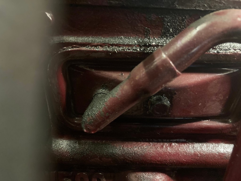
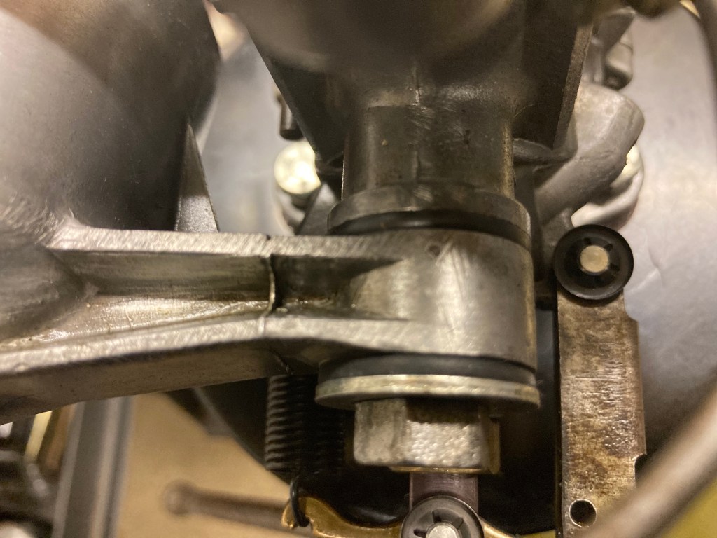
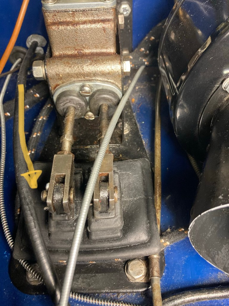
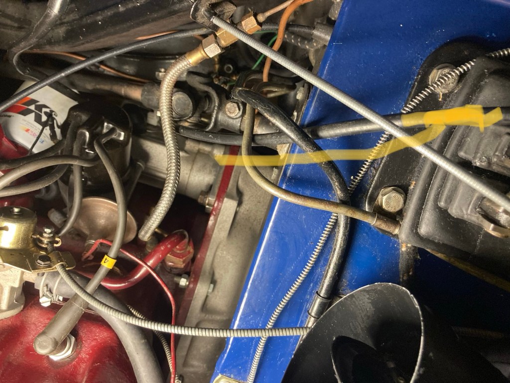
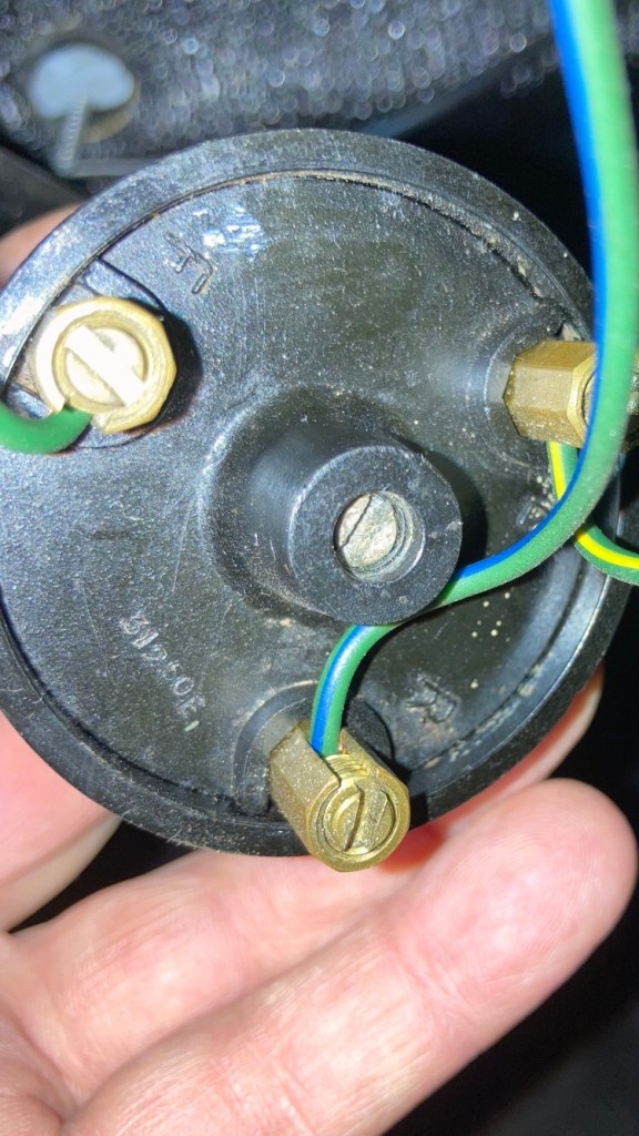
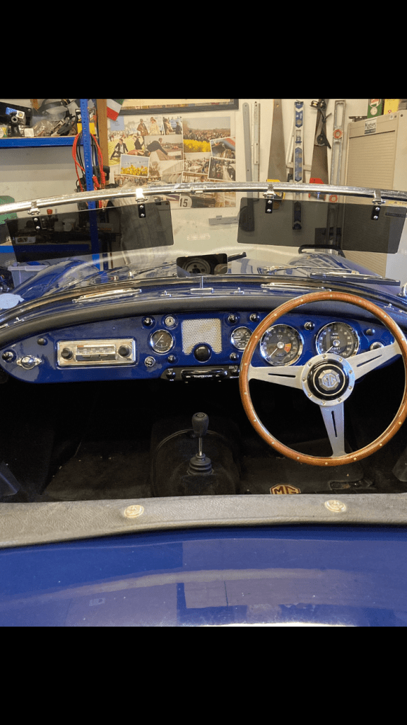
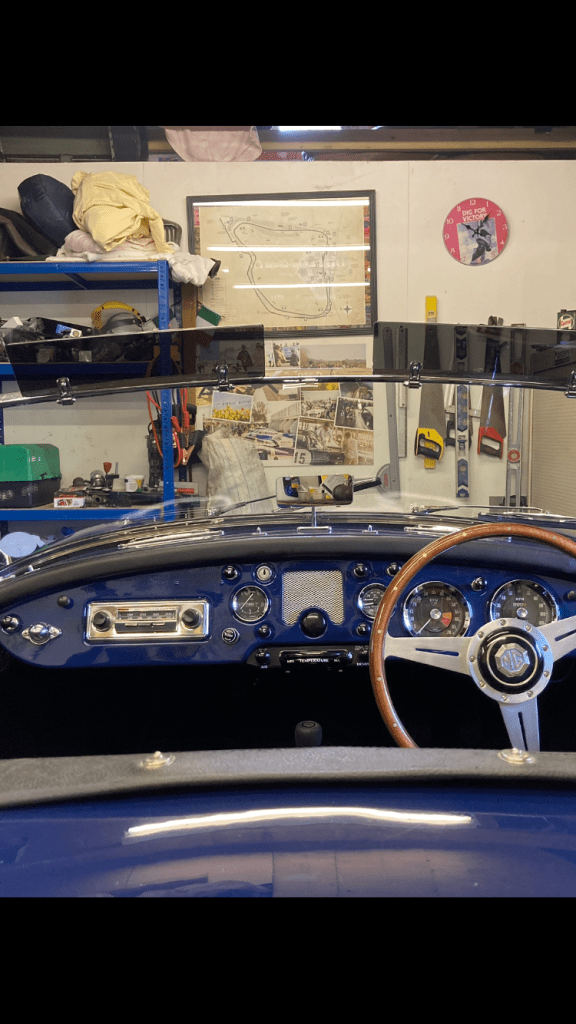
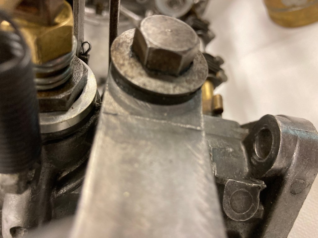
Speedo cable routing – upper end.
I had a question from Ian Catchpole, who is in the midst of restoring his 1957 1500, regarding the routing of the speedo cable at the bulkhead end. The photos of mine may be of use to others. My route may not be perfect but it’s logical. I’ve crudely marked the black cable in yellow.

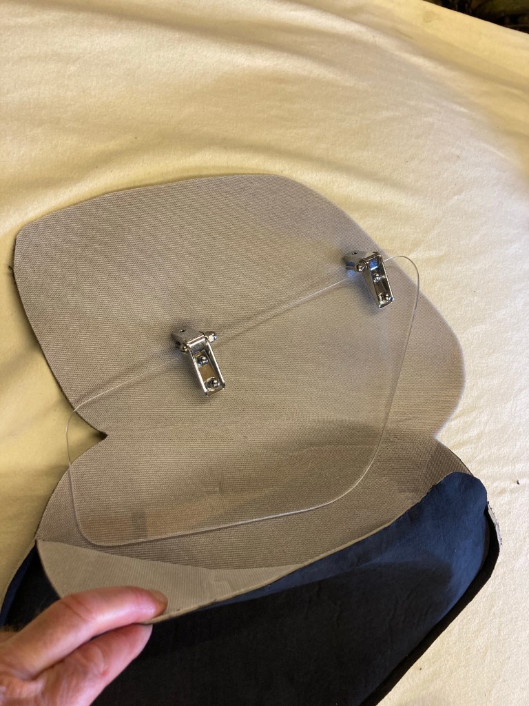
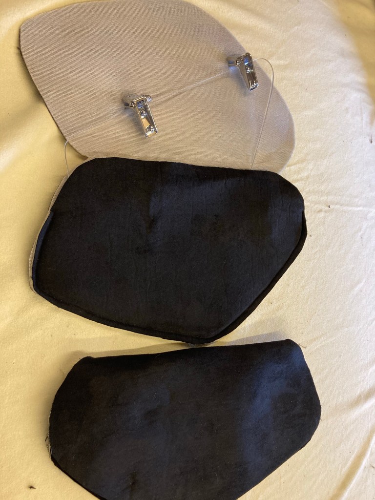
Wind Deflector Storage Bags
The accessory wind deflectors are questionable as to their effect on cutting down turbulence in the cockpit, but they do look good….in my opinion. The problem is what to do with them when the roof goes up and they’re not needed, as they are easily scratched. Up to now, I’ve just wrapped them in old tea towels, but it’s not ideal. In the days before Covid 19, I bought at a classic car show, a roll of black fabric for nothing in particular, but reckoned it might be useful.
My wife is a dressmaker, so I persuaded her to knock up some neat little pocket bags for the deflectors and they turned out well.

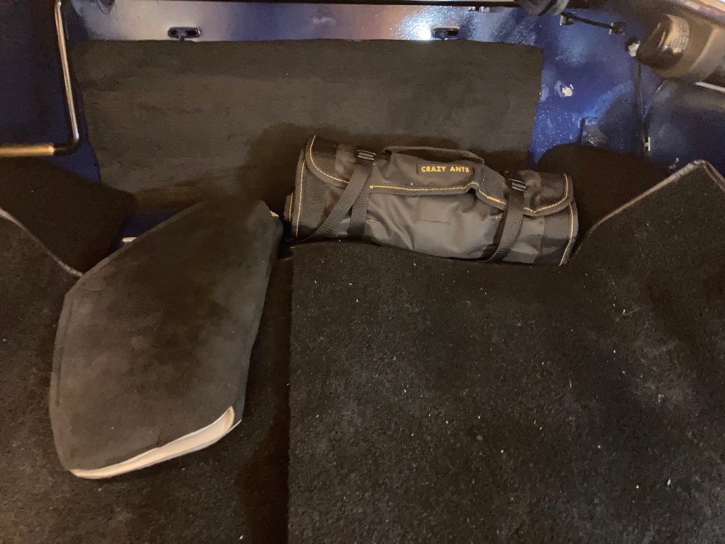
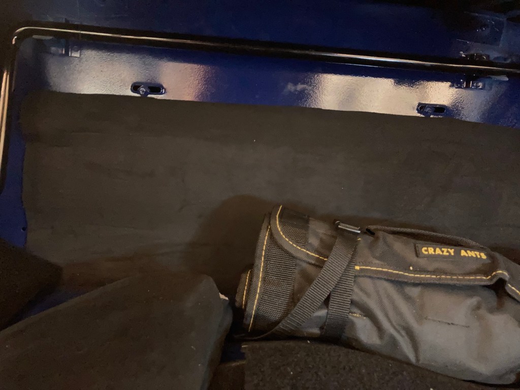
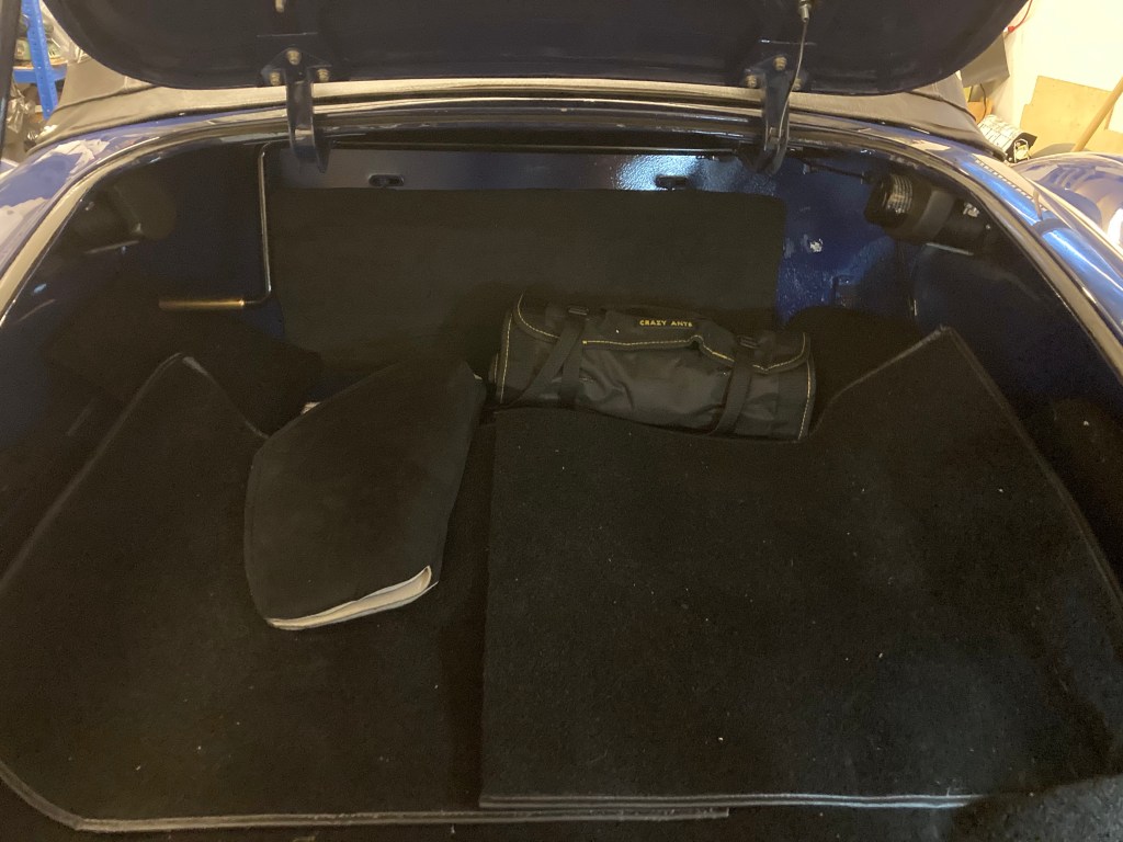
Boot Space/Spare Wheel Removal
The MGA has a reasonable boot space, but it’s seriously compromised by the spare wheel and the kit that goes with it. Add a tool roll and pack of service spares and the space left for two peoples luggage is minimal, especially if contemplating serious touring.
For a while now I’ve been running locally with the spare removed and carrying a standard tyre reinflator and enjoyed the clear boot and the reduced weight. This is fine, but for longer touring holidays, just a reinflator troubles me, as Sods Law, the potential puncture will happen in the most inconvenient place and the reinflator may not be sufficient.
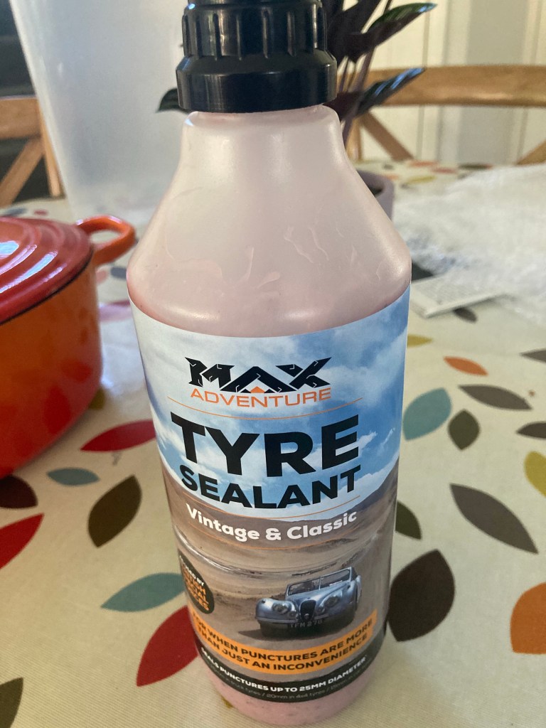
I’ve now committed to a solution (pardon the pun), which involves a product – ‘Max Tyre Sealant’ for vintage and classic cars, which is apparently used by our Special Forces and expeditions, to reduce the impact of punctures. The solution is injected into the tyre and seals the tyre in the event of a puncture and remains soft, so can be wiped out if the tyre needs changing.
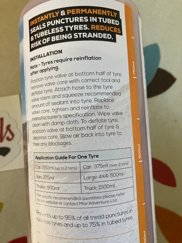

Having committed to this, I’ve removed the spare and the carpet bag cover and made a carpet section to cover the bulkhead hole into the cockpit. This carpet section is secured to the bulkhead with heavy duty Velcro, which means that it’s easily removed if something longer than the boot needs to be carried. The weight saving gained from removing the spare and the Jack is considerable (must weigh it!
Hood/Roof Tweaks
So far, the convertible roof that came from Don Hoods and I fitted myself, has been fine and water tight. My only wish is that I’d managed to fit it a little tighter across the frame, as it thrums loudly at normal speeds.
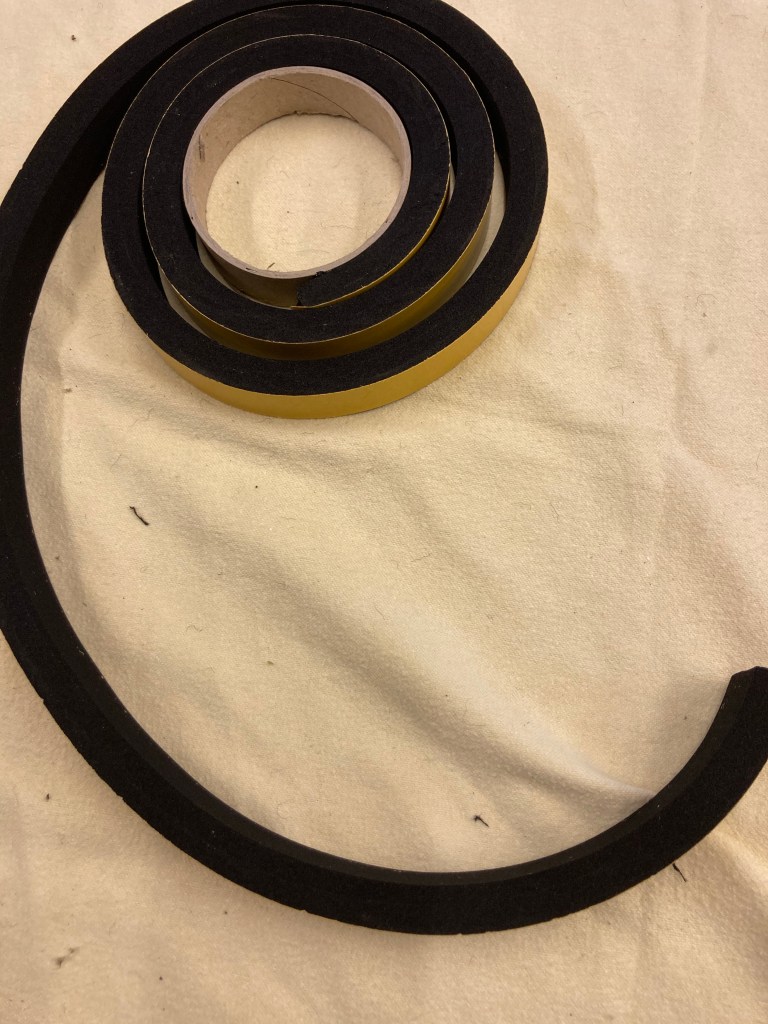
To overcome this, without the trauma of completing refitting the roof, l made a mod, which involves 10x20mm section neoprene sealing strip.
I cut lengths of the sticky backed strip to the length of the two central cross bars of the frame and fed the strip onto the top of the bar, with the adhesive side down.
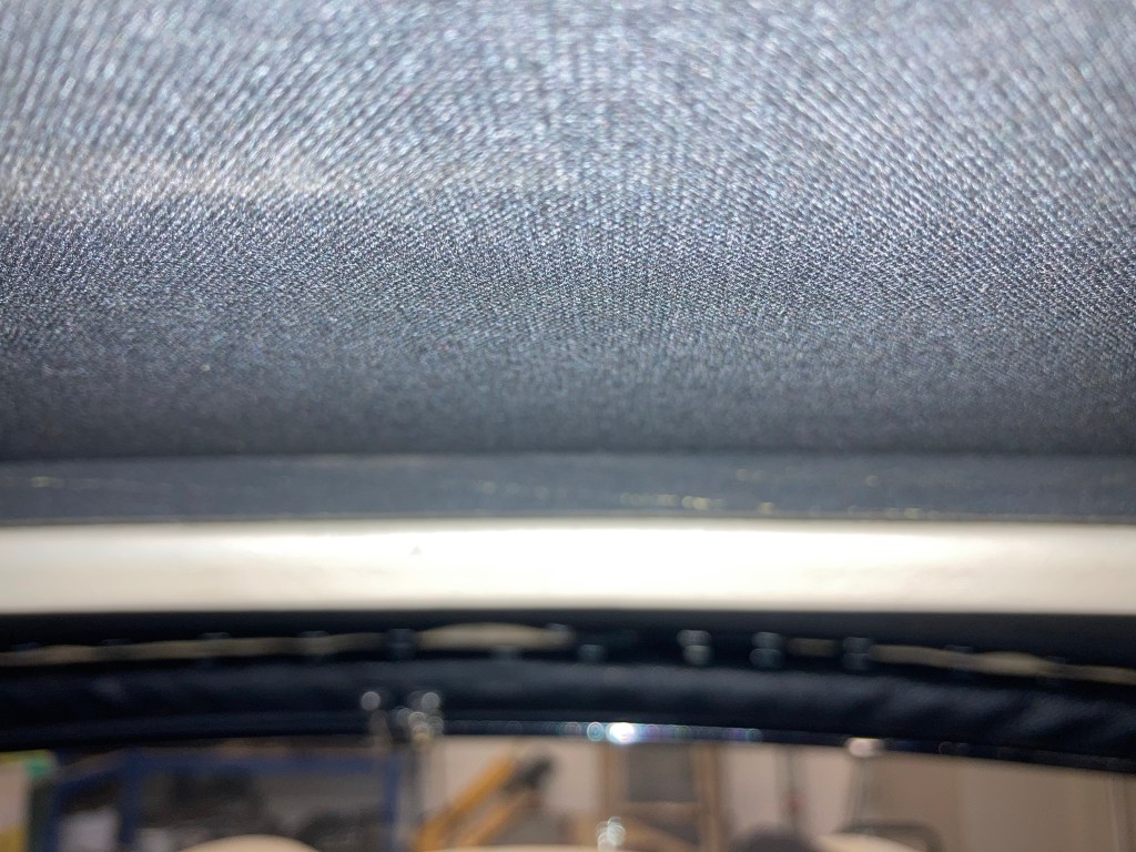
This successfully took up the small amount of slack in the hood, improving the tension in the vinyl and the external shape. Because the strip material is black, it’s not obvious from inside and should remain in place when the hood is folded.
On testing, there is a noticeable improvement to buffeting noise, so a simple and low cost tweak.
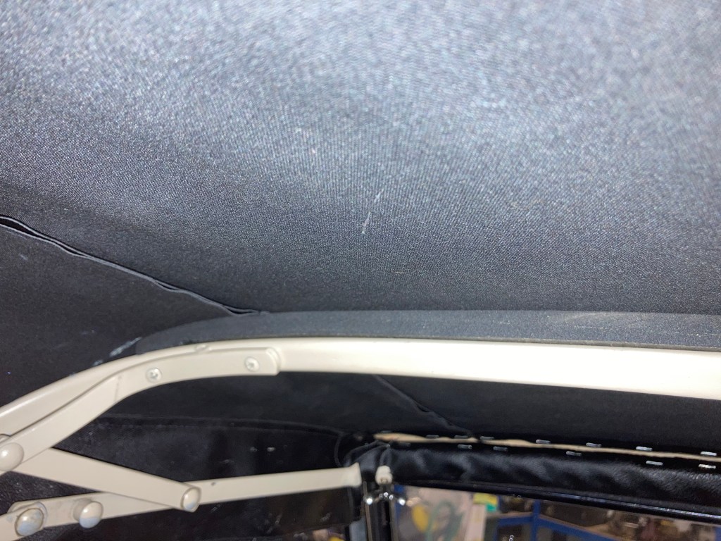
Update. This works while the hood is up, but l hadn’t considered the difficulty the neoprene would add to the already difficult task of single handedly raising and lowering the roof. B
Direction Indicator Issues
Since completing the restoration, there’s been one electrical gremlin that I chose to ignore but knew was wrong and that was the indicator dash warning light, that glowed green permanently once the ignition was on. It would then flash when the indicator switch was activated, but of course, it should’ve been out when not activated and flashing.
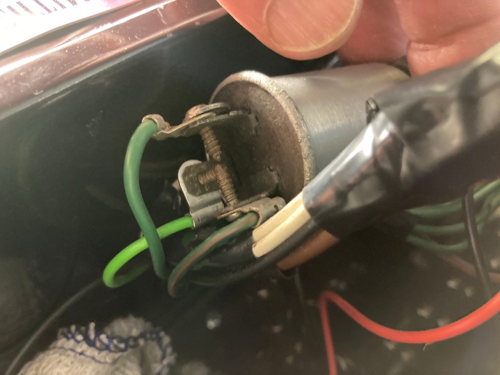
I checked the wiring diagram and could see that the light green cable to the dash warning light is fed directly from the flasher unit, located on the bulkhead. On inspection, I noticed that two of the three terminal screws were touching, one being the light green, which was getting a full direct current.
I removed the unit, removed the terminal screws, cleaned them up and refitted the screws with washers to space them and prevent touching. Problem solved.
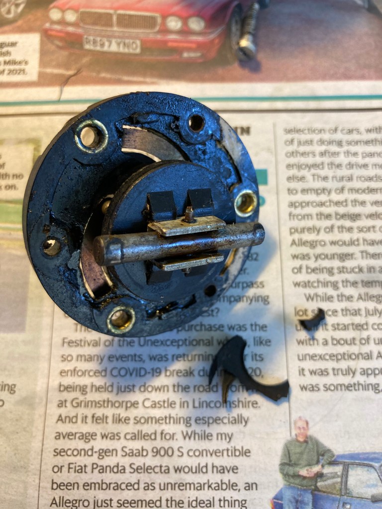
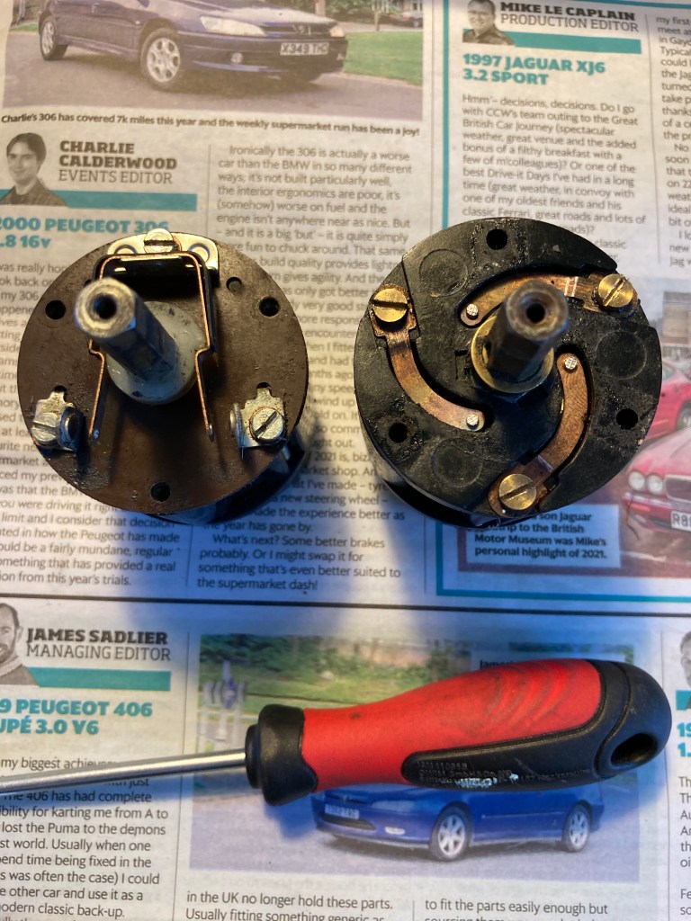
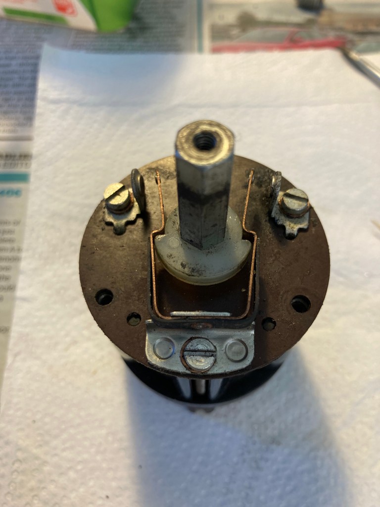
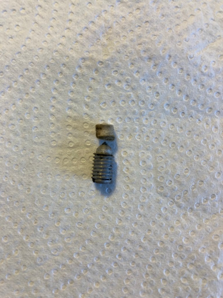
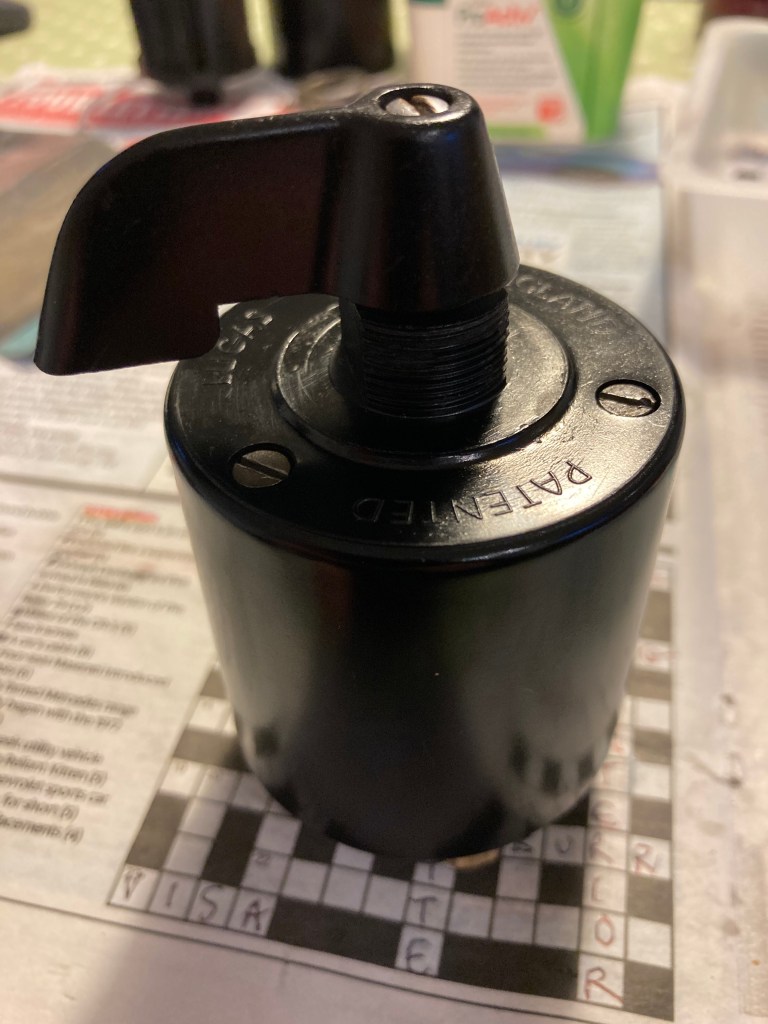
Direction Indicator Switch
The indicator switch had started to show signs of wear and typically was not staying on as long as it should, on the left turn. This indicated that the vacuum feature of the switch that provides the delay, was not functioning. The original switch was removed during the restoration to be overhauled, but I dismantled it and didn’t get around to completing it, choosing to fit an old unit bought at an auto jumble.
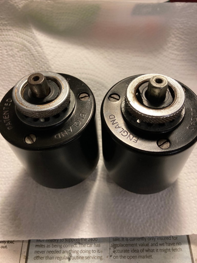
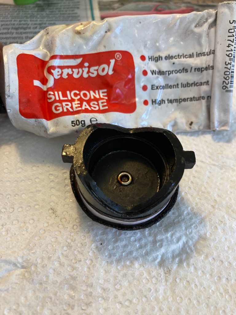
As a winter job in 2020, I decided to set about overhauling both the original and the replacement.


Flasher Relay.
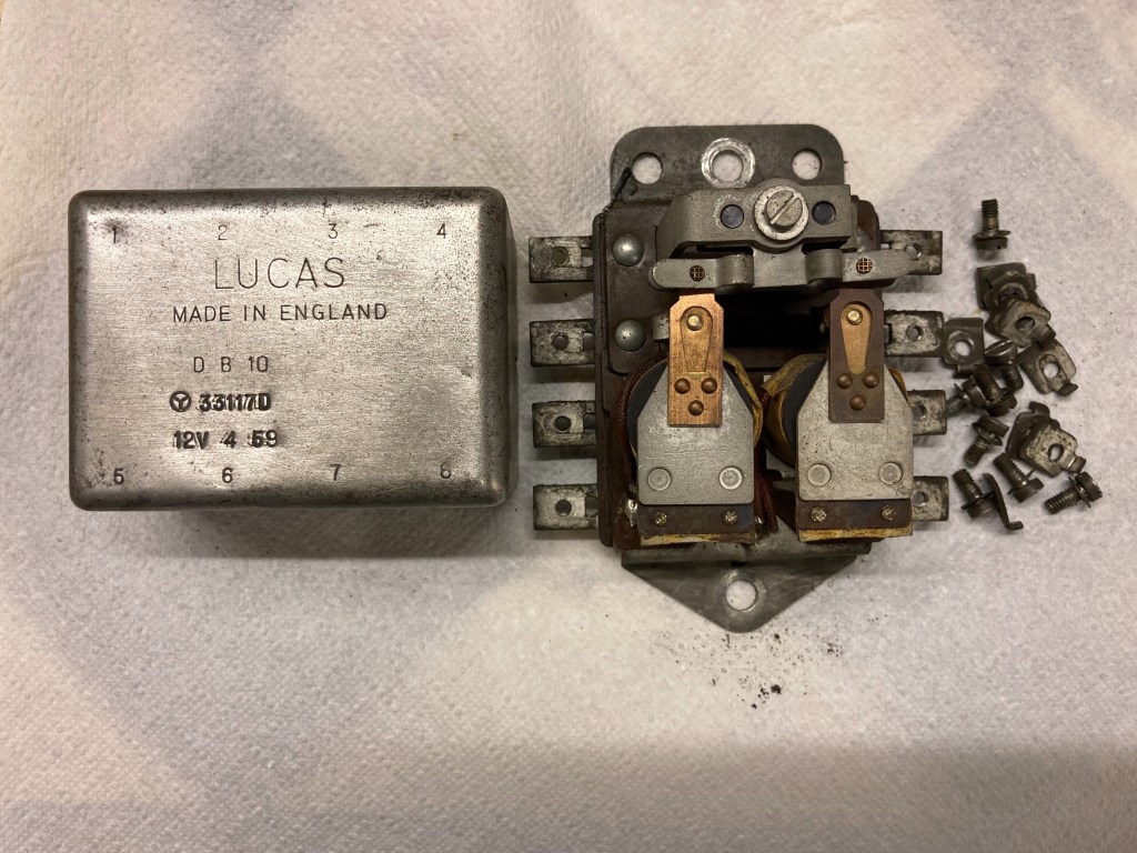
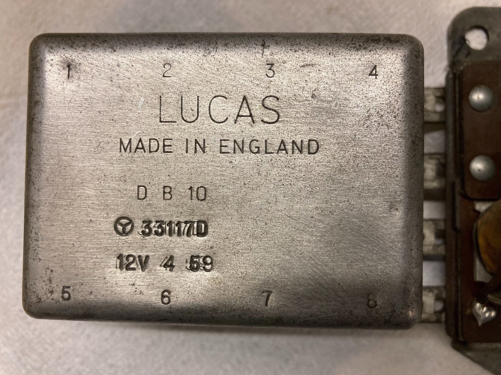
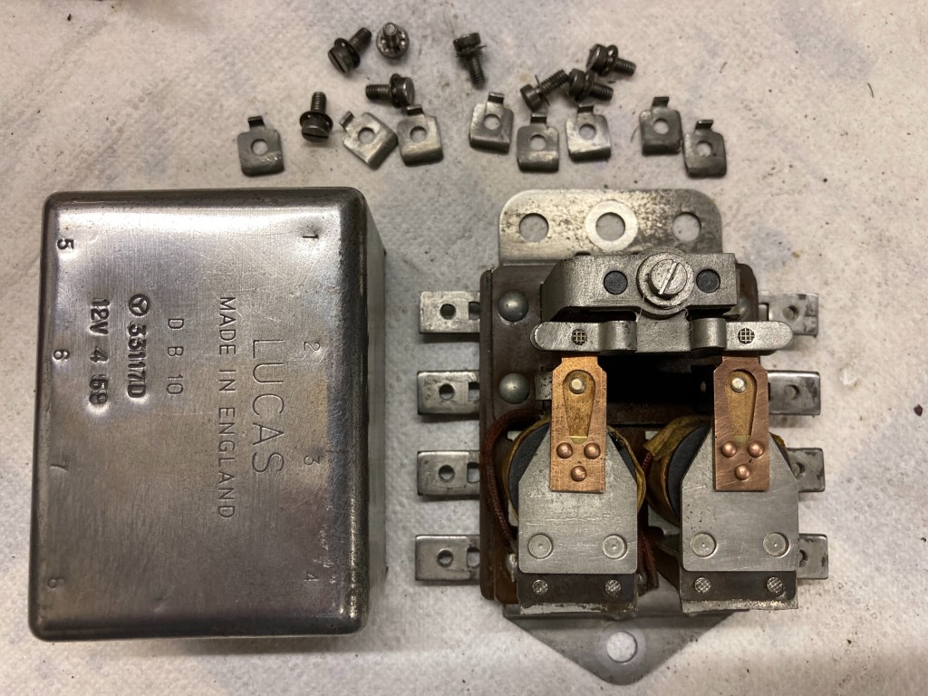
Having sorted out the flasher switch and flasher unit, there was still an intermittent problem with one side flashers, so I decided to have a look at the relay box that is unique to the 1500. Mine is the original unit that dates from April 1959 and has remained untouched since then.
The relay box cover is held on by tabs on the bottom edge, bent over the edge of the base and inaccessible without removing the unit from the bulkhead. Once removed, to release the cover the tabs need to be bent back and then a thin screwdriver used carefully to prise the cover off.
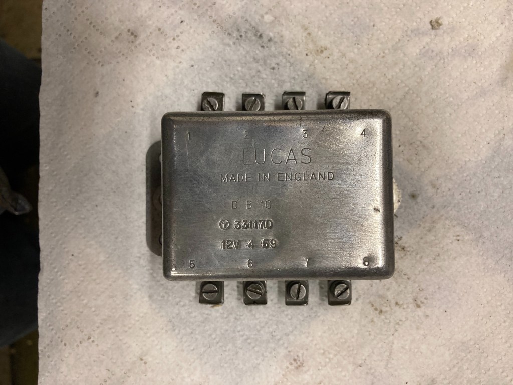
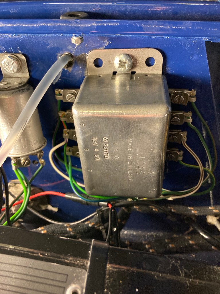
The relay requires a good earth through the body, so I removed excess paint around the bulkhead bolt holes.
Rear Direction Indicator Upgrade
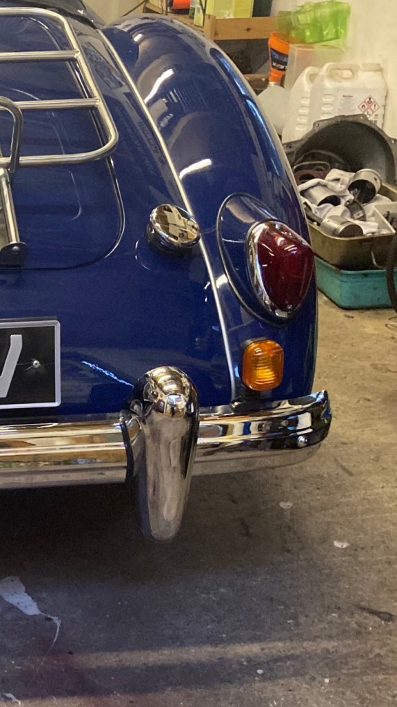
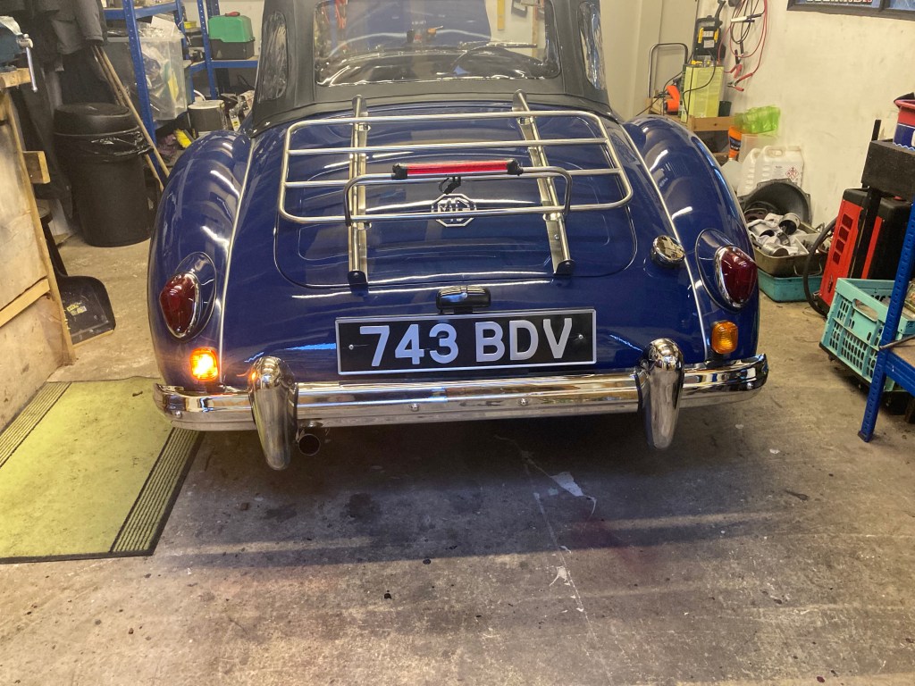
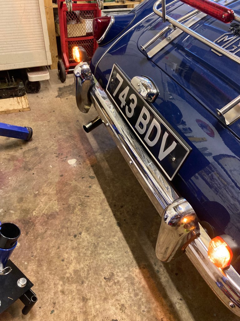
I’ve already fitted a third, higher level LED brake light, which has made a noticeable difference, but there was still the issue with the red indicators. I’ve mused on the options for a while now and decided I needed a winter job. I considered changing the 1500 lamp for the later 1600 plinth that has the same Lucas red lamp, but also a separate amber direction Indicator lamp above it. My problem with this solution was that it changes the pure lines of the 1500 in a material way. Also, the cost of a pair of 1600 plinths, due to their rarity, is excessive.
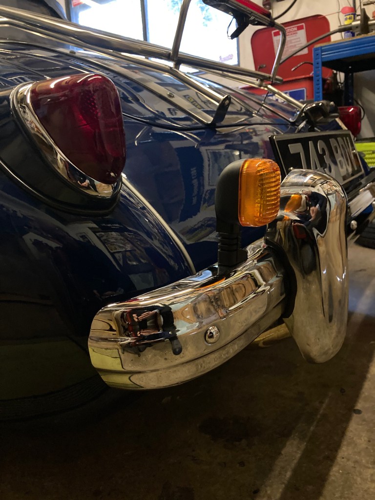
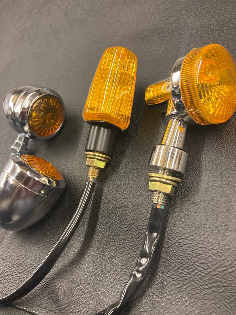
I wanted to avoid drilling the bodywork and for the fitment to be reversible, so my decision was to fit a pair of motorcycle sized lamps into the rear bumper.
These were the alternatives I considered. I decided on the more modern looking black type, rather than chrome, as they are less obvious.
Wiring. The aim was to have only the amber flasher working and the red lamp purely for brake lights and sidelights. Because the 1500 had a shared brake light/flasher, enabled by the unique relay, the wiring needs to be changed. For full info on this, MGA Guru Barney, has every last detail on his site. Basically, it’s a case of separating the wiring from the flasher element of the rear light unit to feed the new single filament lamp and provide a new, separate feed wire from the brake switch to the two rear double filament brake lamps.
I already had a wire from the brake switch, following the loom along the chassis rail, to feed the 3rd brake light, but fitting one is easy. This wire then needs to split off using a three-way connector, to each brake light. This new wire is fed into the back of the lamp plinth into the lamp and connected up to the brake light terminal.
The indicator feed wires are white/blue for the left hand, white/brown for the right and these are disconnected from the lamp terminals and joined directly to the new amber lamp wires. That leaves the earth, ground cable from the new lamp, which l connected to the ground terminal in the old lamp. All my connections were made in the old lamp, so are nicely hidden when done.

The only change required to the flasher relay, is to disconnect the green/blue wire from terminal 5 and from the brake switch (if you don’t, the new amber lamps will light up with the old brake lights!). l drilled the upper bumper surface to accommodate the wires and retaining bolt of the new amber lamps.
Hazard Warning Lights
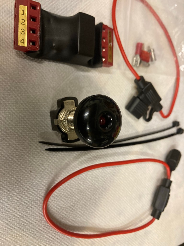
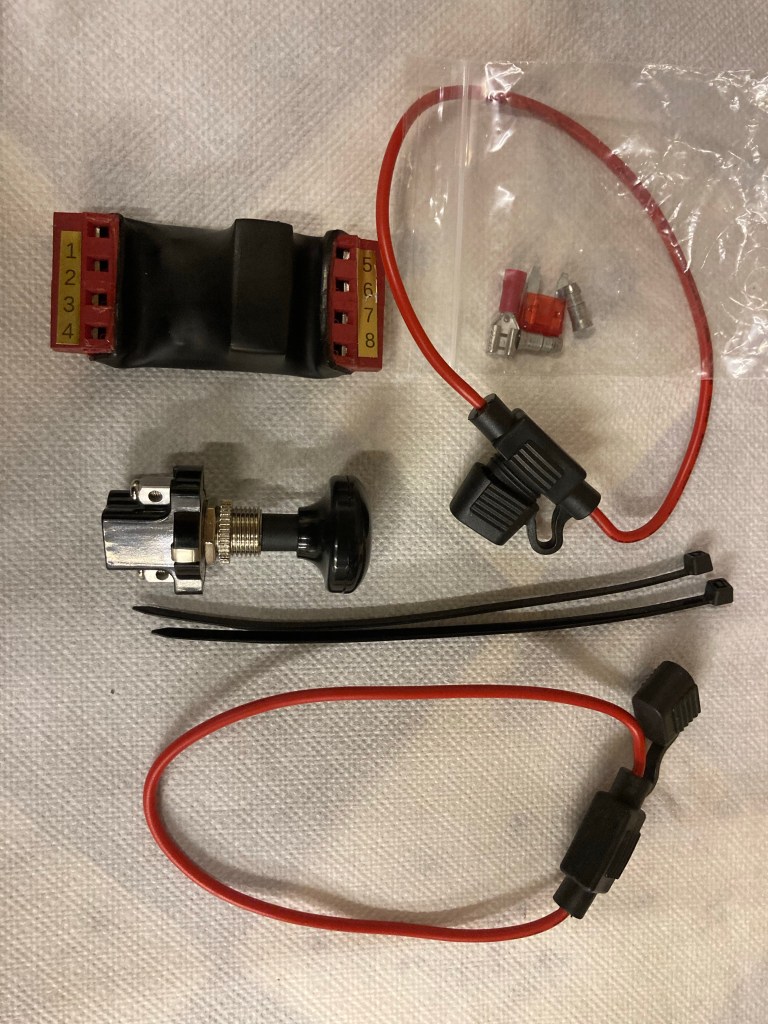
Back in May 2023, l had the misfortune to breakdown with a seized engine on a difficult stretch of busy dual carriageway and without hazard warning lights. It was a scary experience and one not to be repeated, so I looked for a solution.
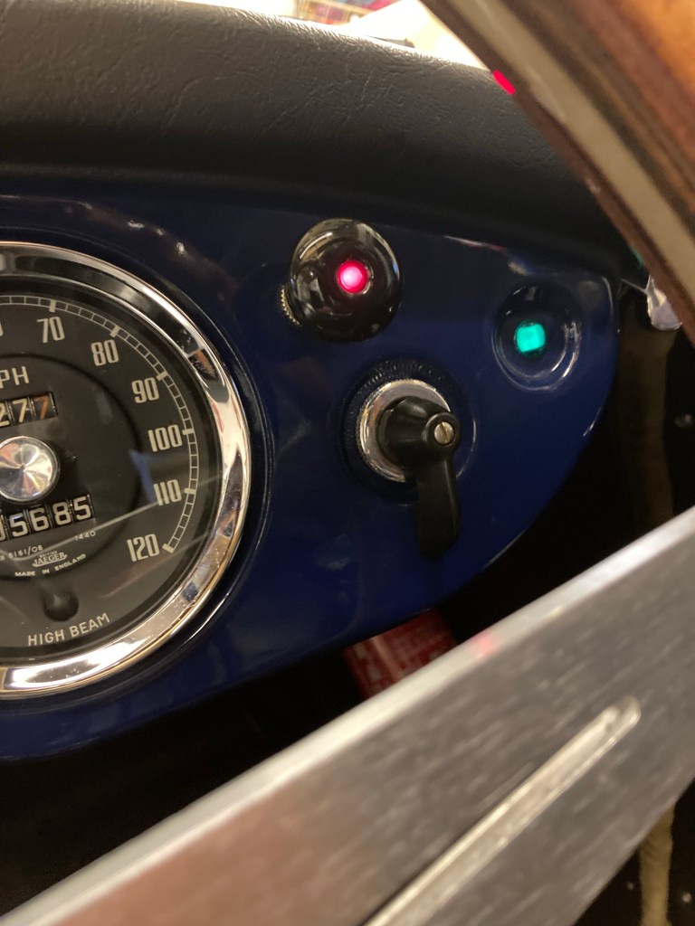
There are various kits out there, but the kit that I went with was from ‘Retronics’ at about £40. It’s aimed at classic vehicles and caters for vehicles fitted with the Lucas relay serving the single rear combined brake/indicator/sidelight set up. I also liked the black, domed switch with red flashing light, as it fits in discreetly with the other dash switches. It’s a relatively easy fit, but if help is needed, the two guys who run the business are extremely helpful.
Sun Visors
I often take the A out for a late afternoon spin on a fine day and it usually involves driving into a low sun, at some point. With the roof down and no sun visors, I’ve relied on a peaked hat and sunglasses, but it’s not really effective.
I recently saw a pair of tinted visors on a TR3 and gleaned from the owner that they were a Tourist Trophy product, bought through Moss. So I bought one in a Moss discount sale to test on the A. It’s ideal, fitting onto the top edge of the windscreen frame by slim clamps, each with a small Allen grub screw, identical to T T’s side wind deflectors.
I also tried it with the roof erected and provided the underside of the roof header has a soft sealing strip as mine does, it seals over the visor clamps, without leakage.
They’re not cheap at £36.00 inc postage each from Moss, but worth every penny in practice, offering a really excellent sun filter.

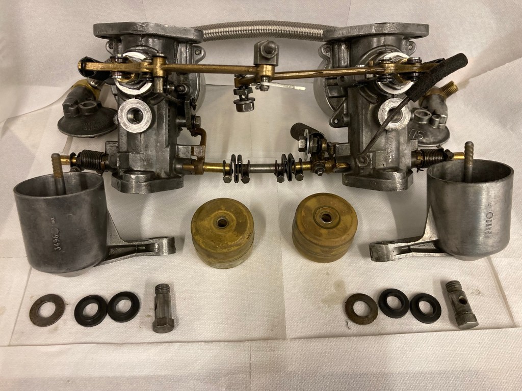
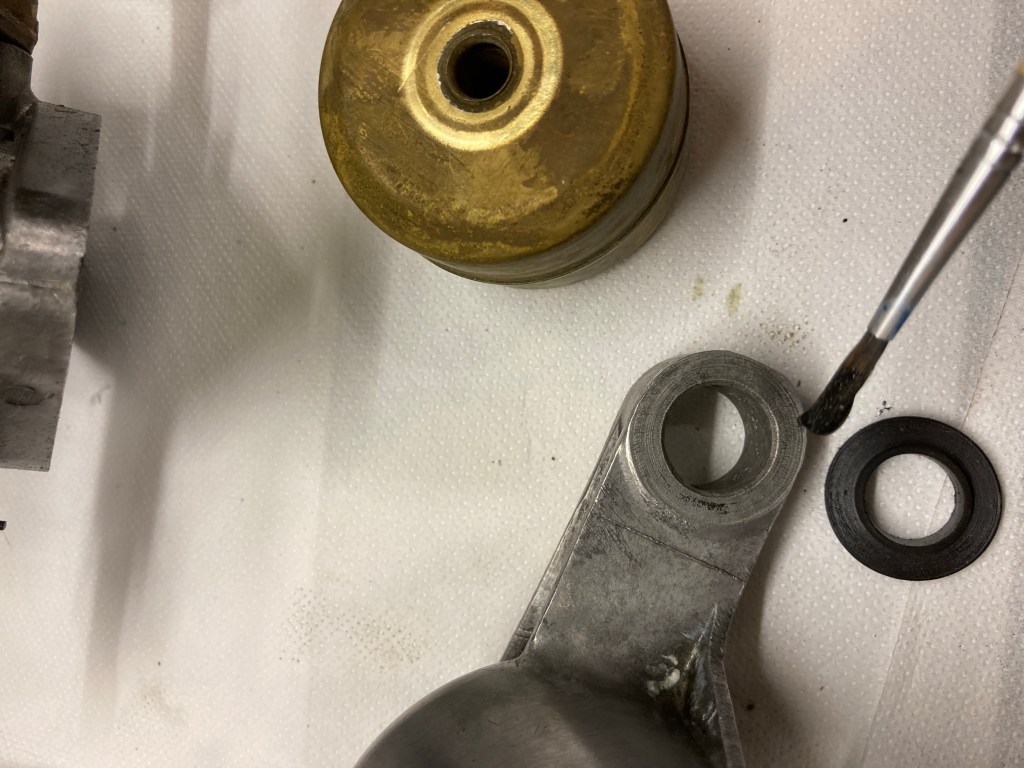
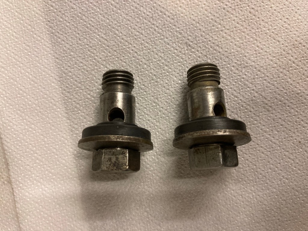
Fuel Leak (Take 2)
Despite new rubber seals, the carb fuel bowl union with the carb body, continued to weep. Nothing major, but enough to keep a smell of fuel lingering. Attempting to do this job in situ is almost impossible and a waste of time, much easier to remove the carbs and do the job on the bench.
I fitted a new set of seals, but this time I used a smear of Loctite 5922, which doesn’t set hard and is fuel resistant. I use a small artists brush to smear the gasket paste on each surface of the seals and the dished washer under the bolt head. Care must be taken not to get sealant on the shaft of the bolt as it could block the fuel hole. Also making sure the washer is of the original dish shape is important, as that helps stop the lower rubber seal from spreading.
Finally, taking care not to over tighten the bolts helps maintain the seal. This time, no more leaks.

New Air Hoses
The air hoses I sourced during the restoration were from Moss and were slightly undersized in circumference and almost impossible to fit without splitting them. I put up with them, but recently found the correct size at Brown & Gammons which I bought and fitted.
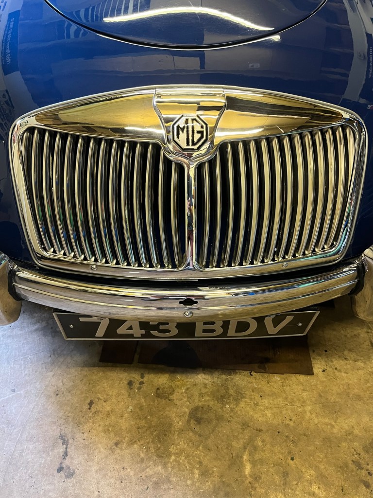
To do this job properly requires removal of the grille, as the tubes follow a tortuous route and need to be fitted through the retaining hoop clips that can’t be accessed with the grille in place.