Cable and Pipe Routing.
Getting the correct routing of all the pipework and wiring is a challenge when faced with rebuilding, so this section aims to help the process with some pictures of pre-restoration and some following the work.
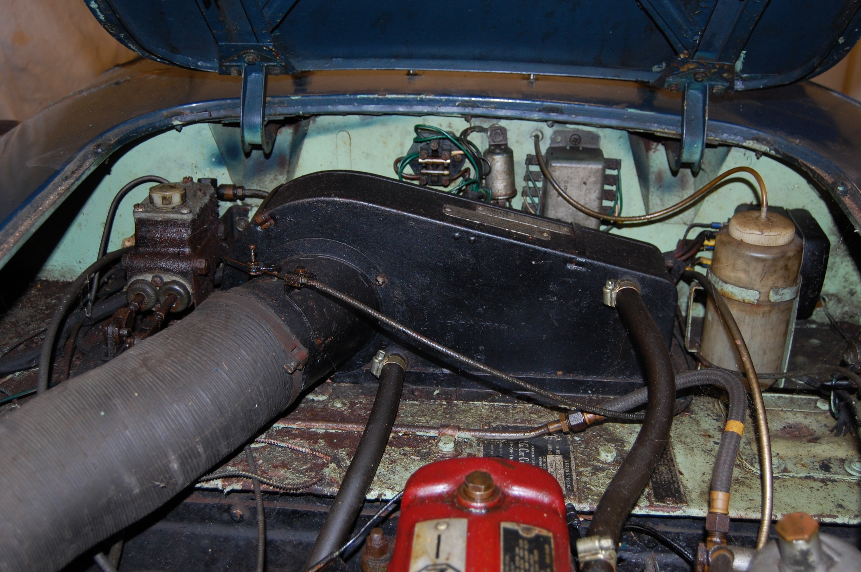
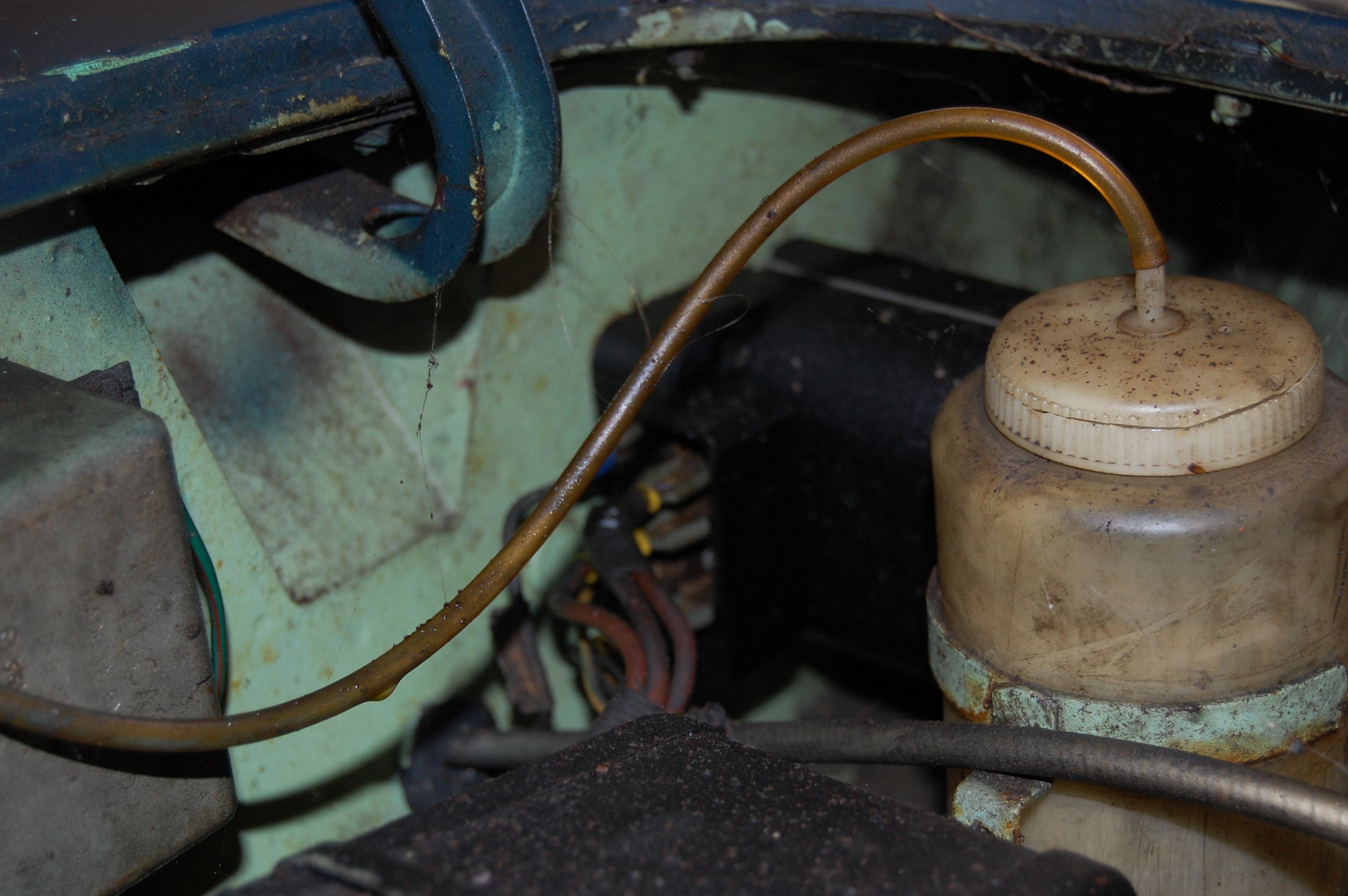
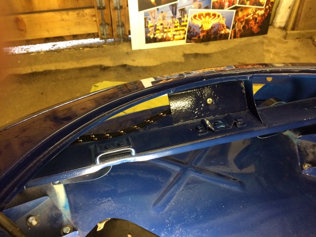
Original underbonnet – note position of fuel feed pipe.
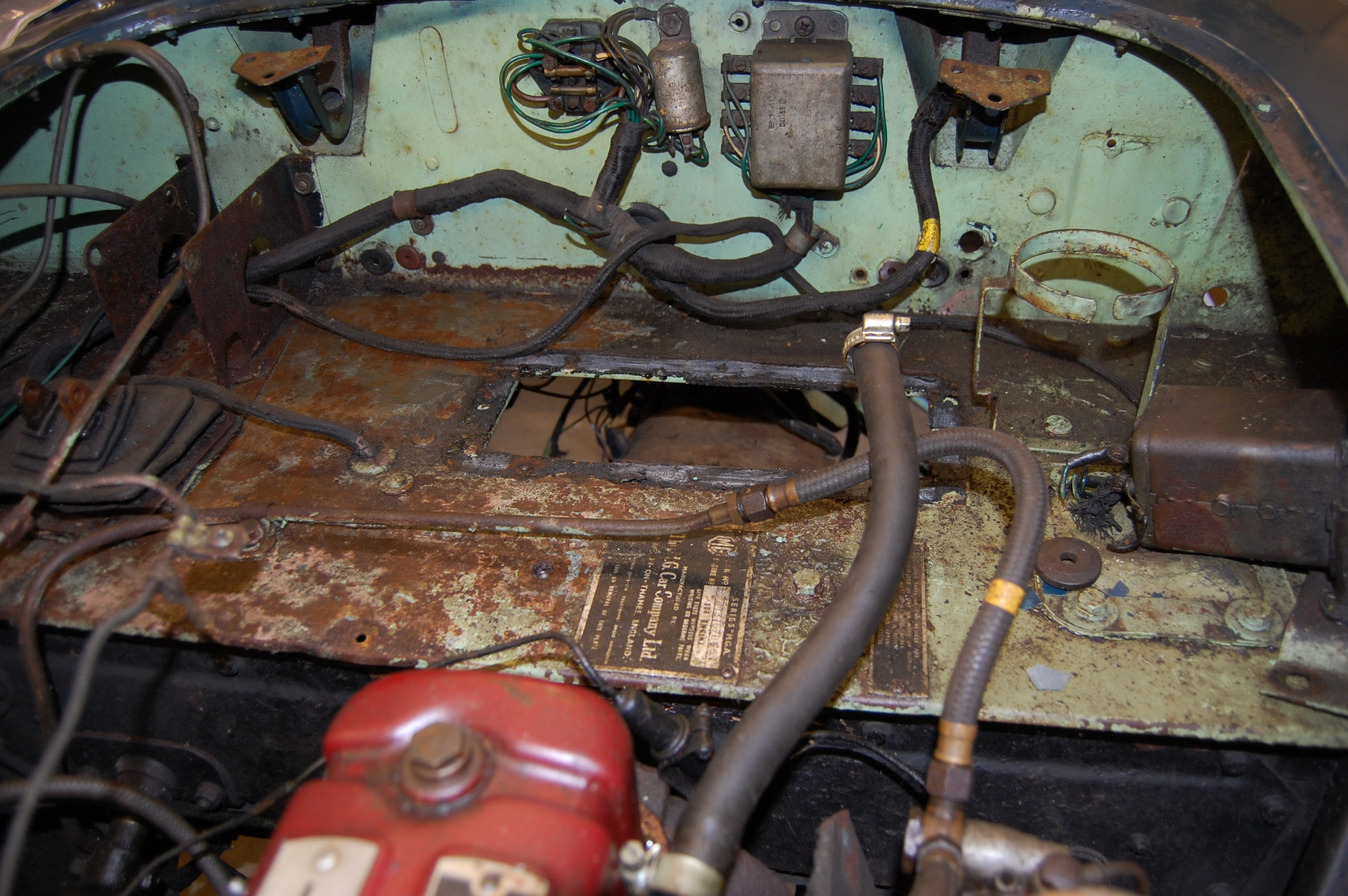
Full Strip down of body in readiness for removing the body.

Left to right – Clutch pipe, master cylinder to slave cylinder – brake pipe, three-way union to rear brakes – main battery to solenoid cable – fuel pipe, fuel pump to carbs.
Fuel pipe from pump to carbs. The lower pipe is the rear brake pipe showing the attachment point on the right-hand battery carrier.
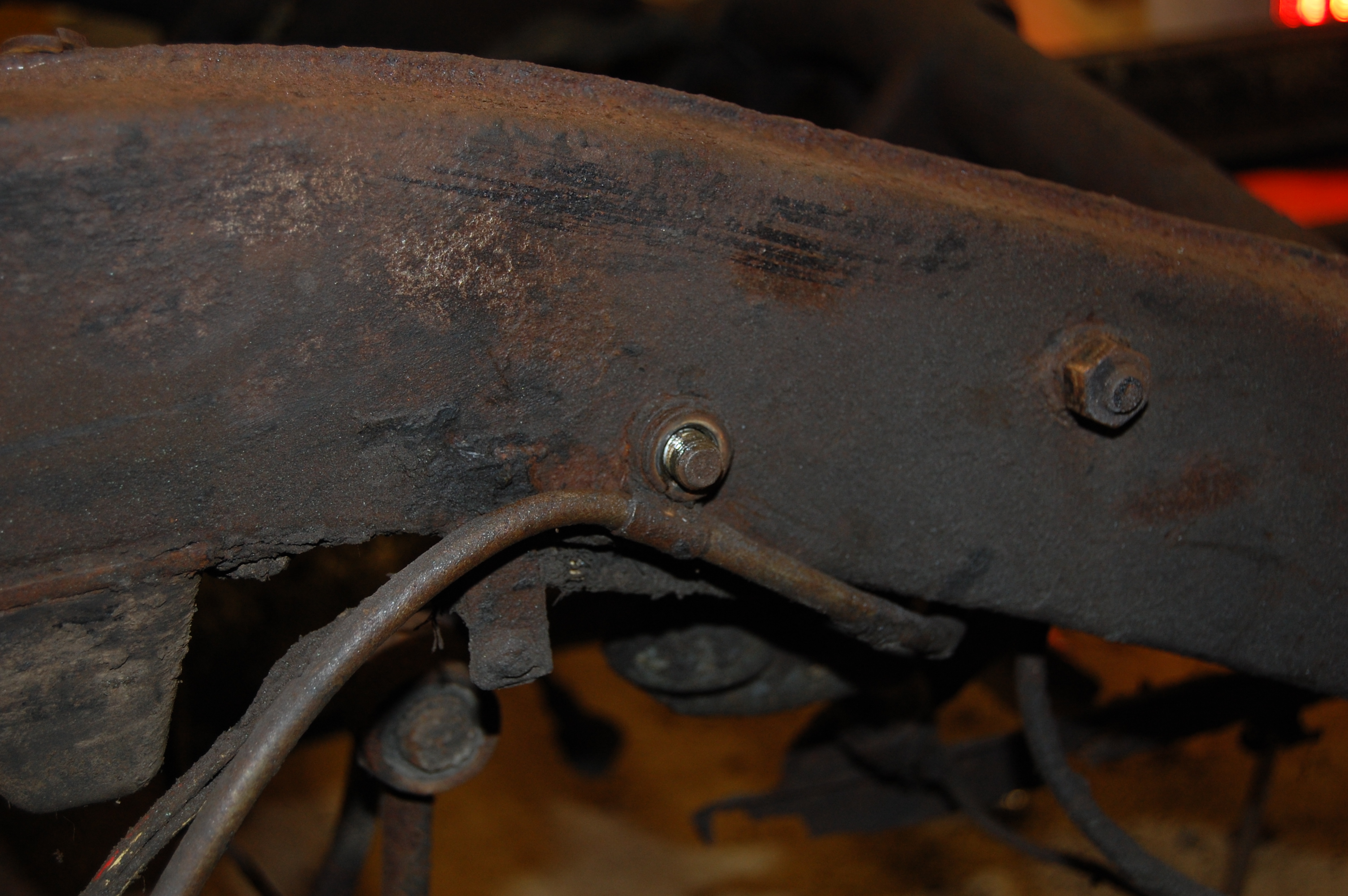
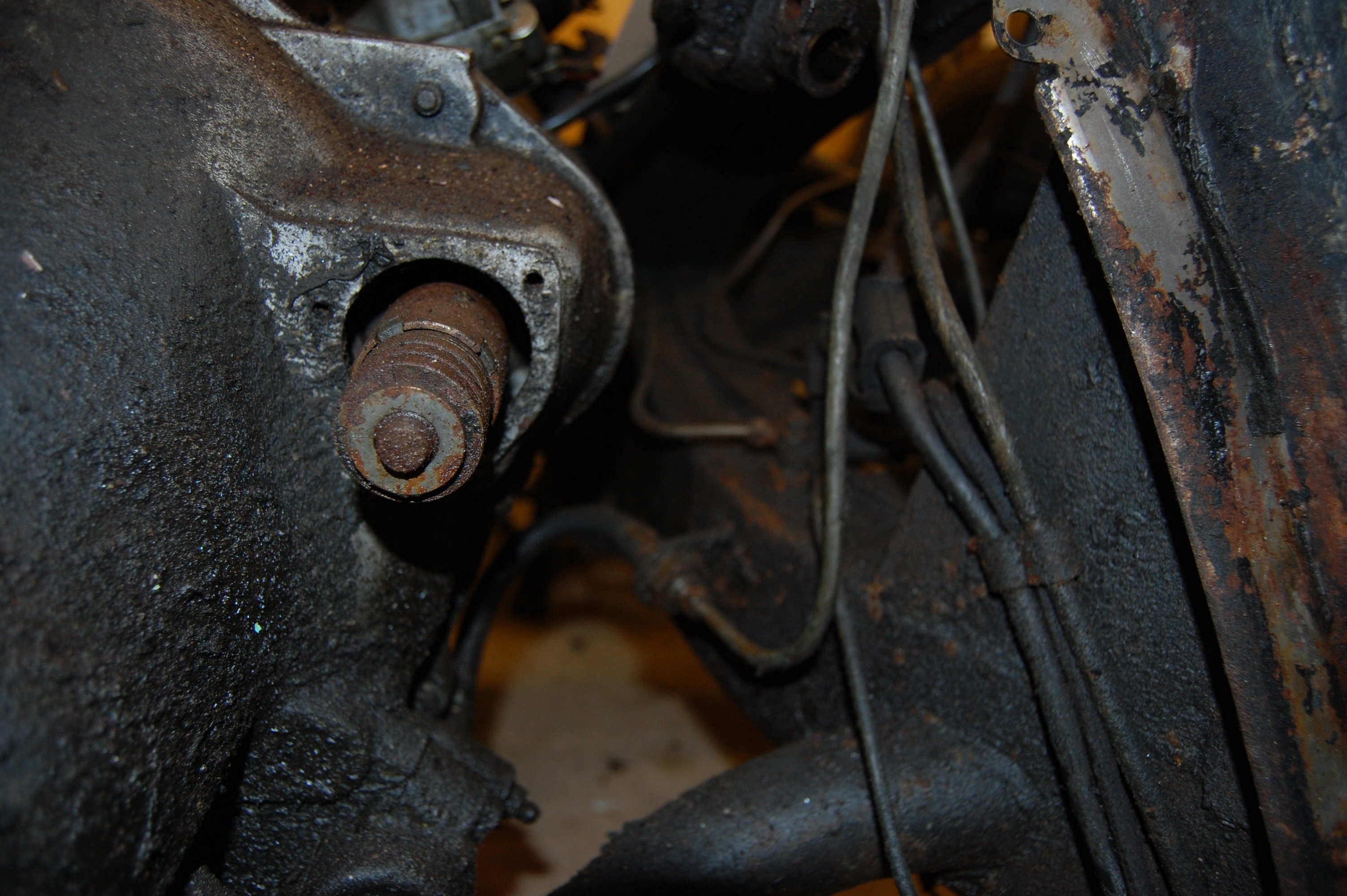
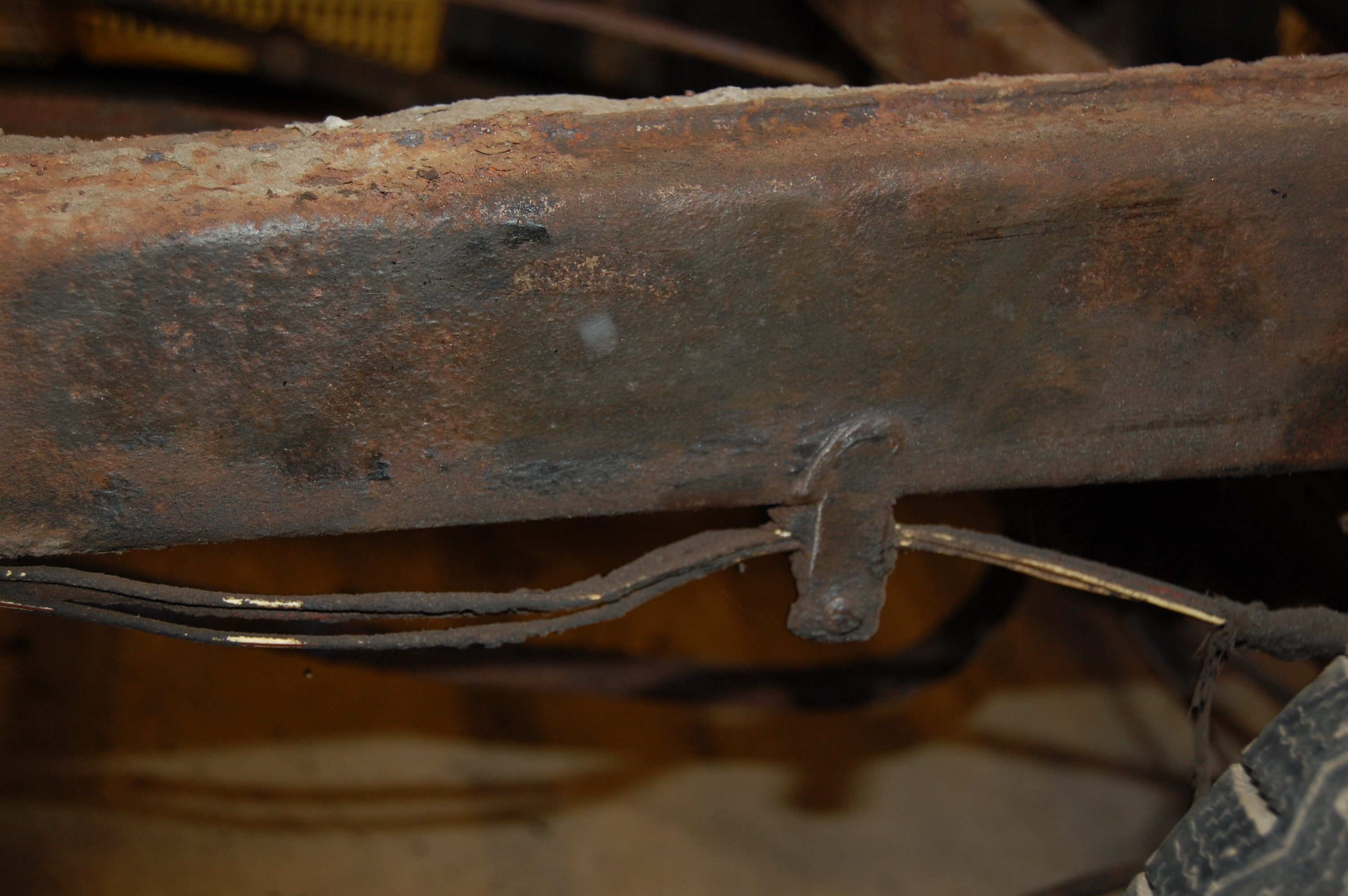
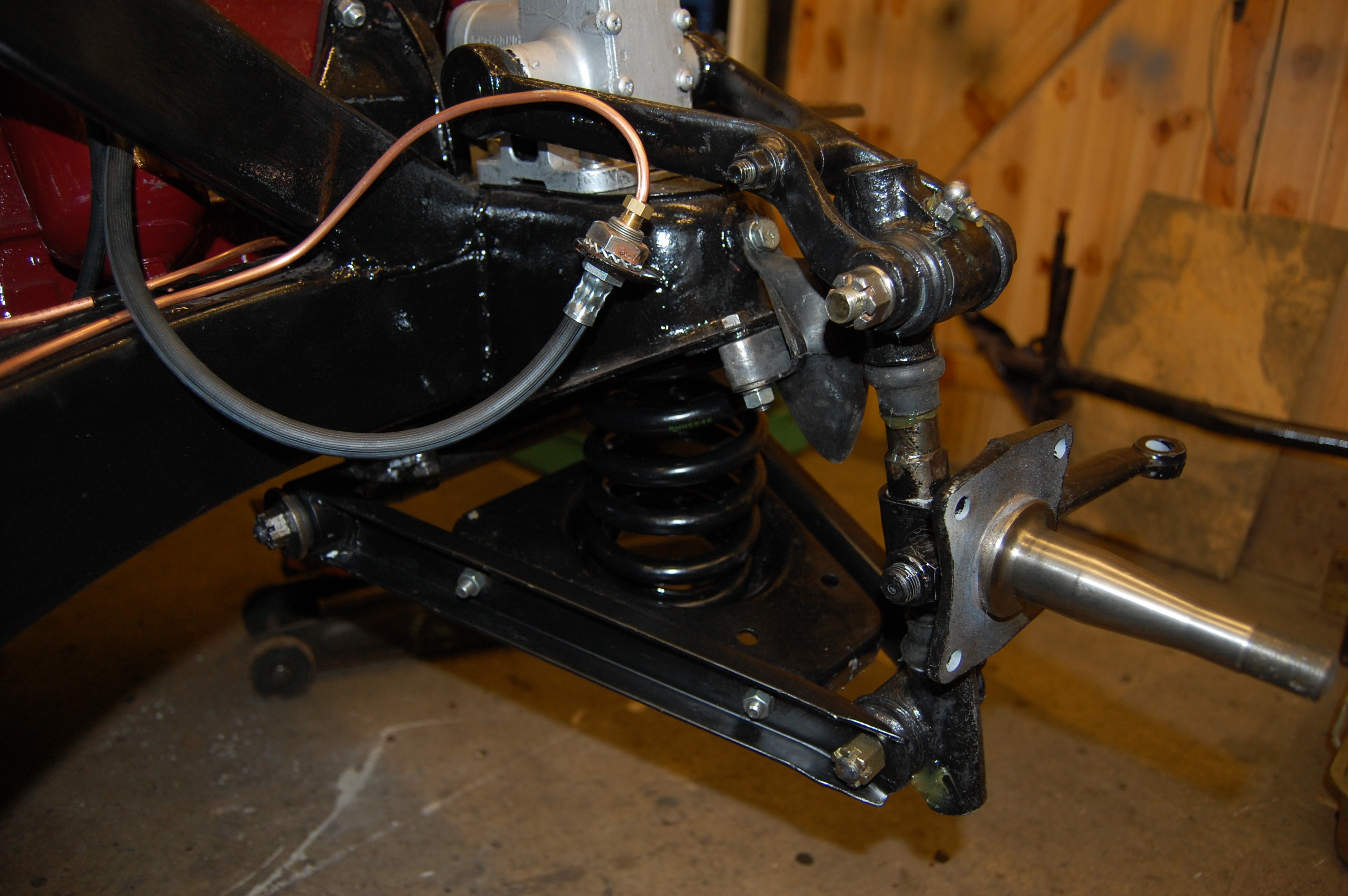
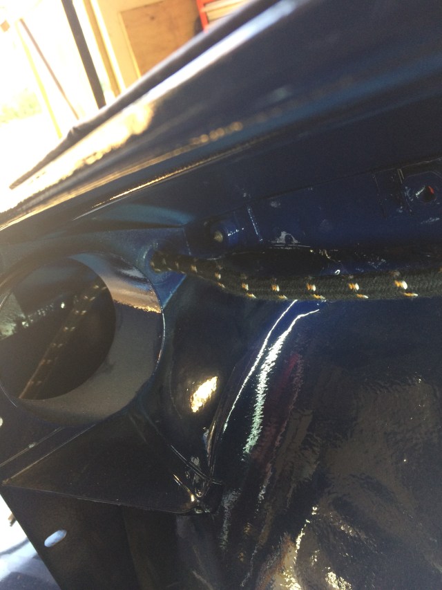
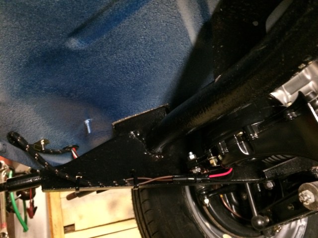
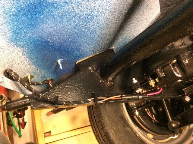
Fuel pipe from tank to pump runs outside of chassis and locates to the lower shock absorber mounting bolt.
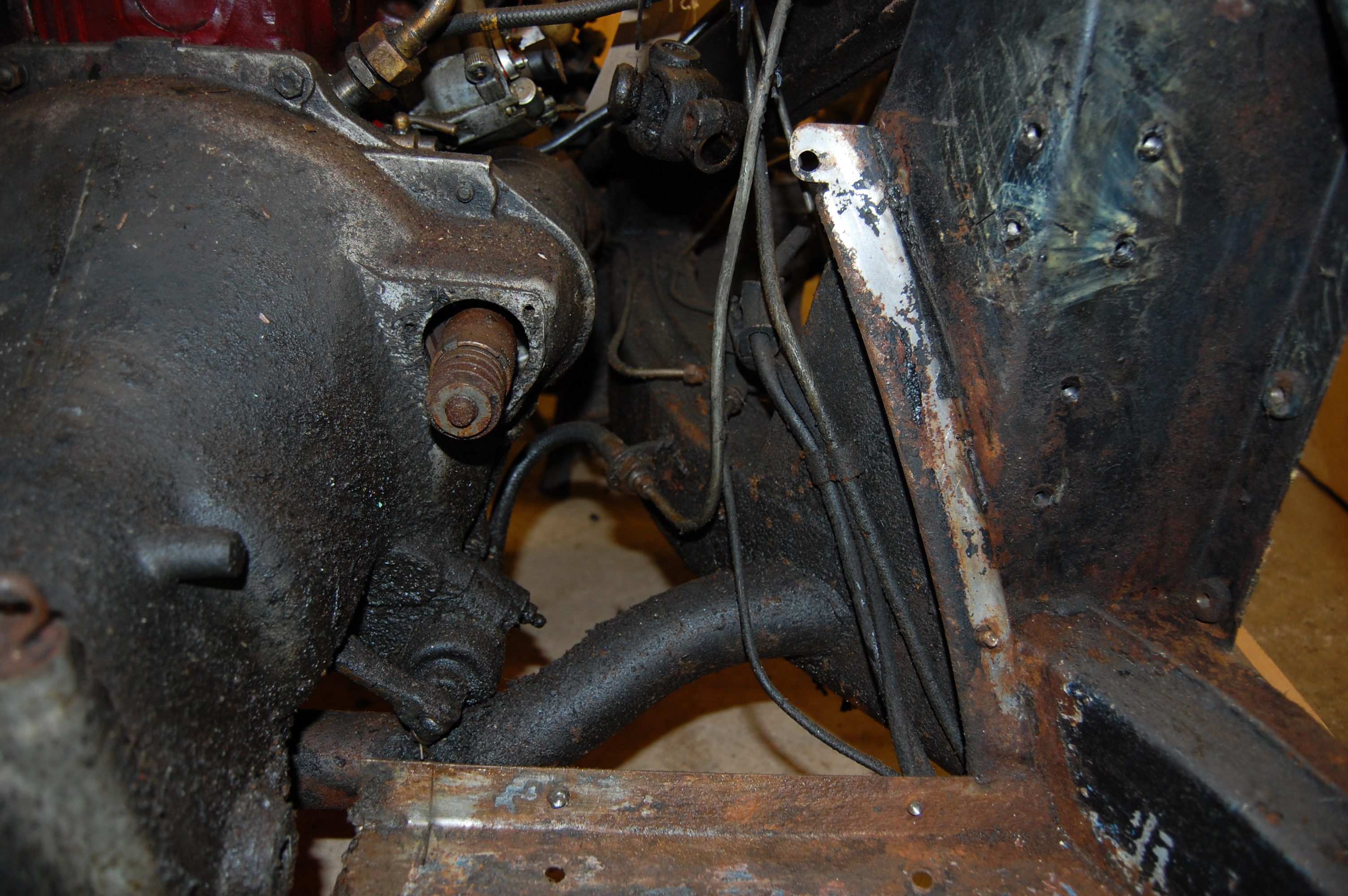
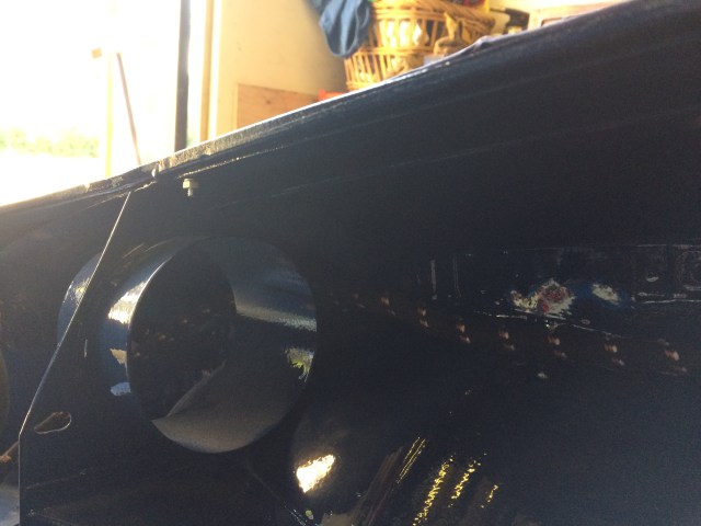
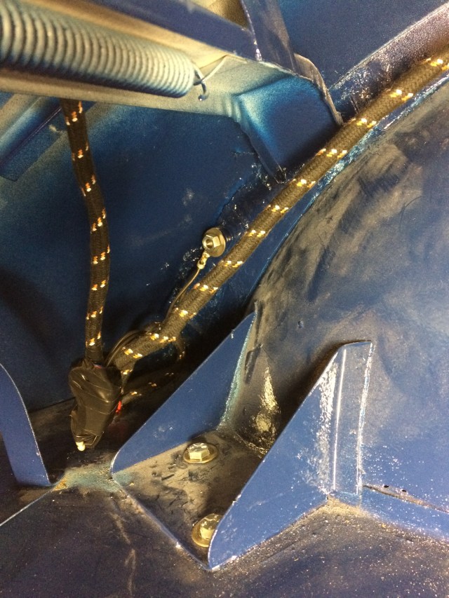
This shows the position of the wiring loom in relation to the fuel pipe, with the spur to the tank sender unit.
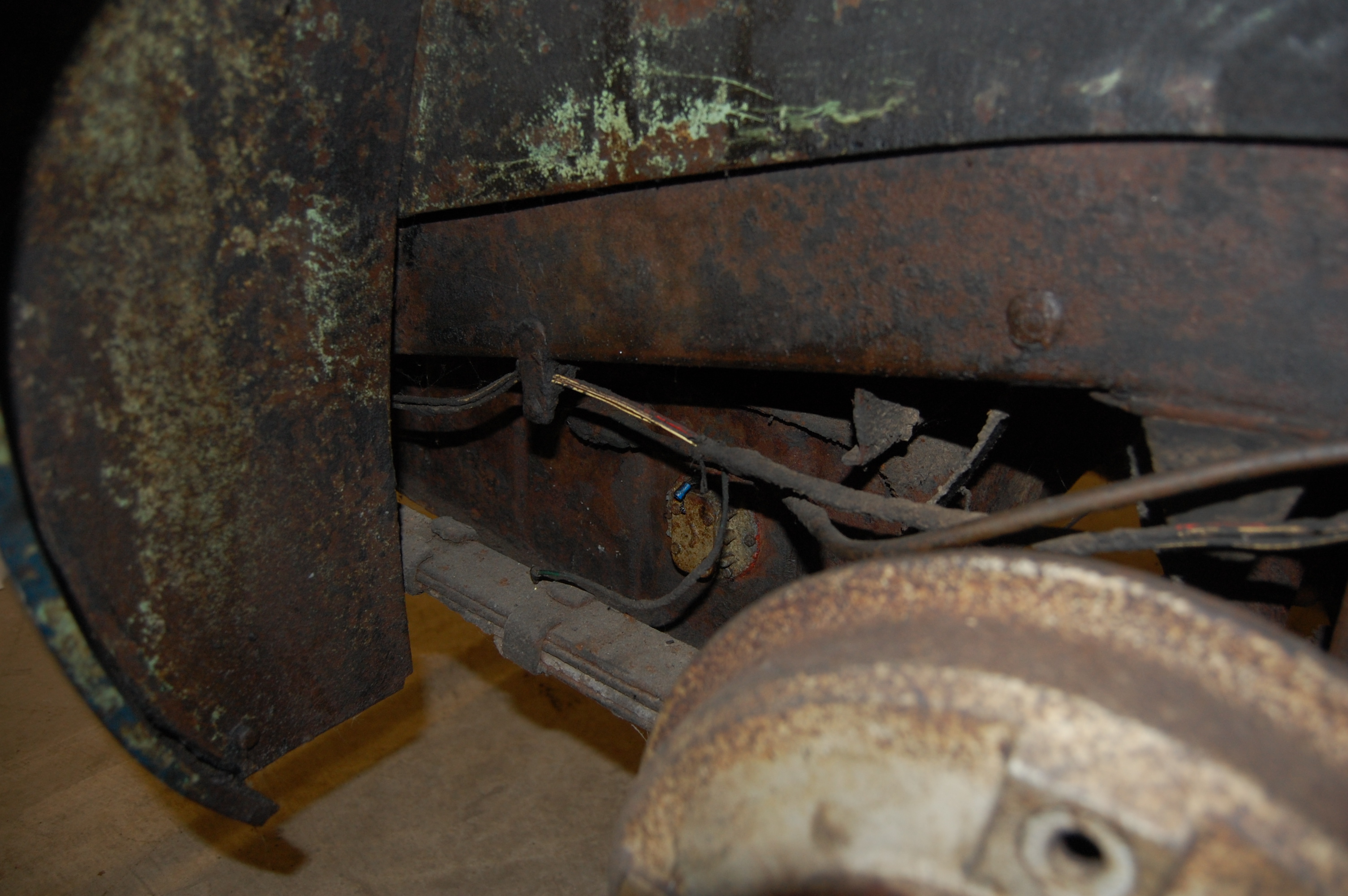
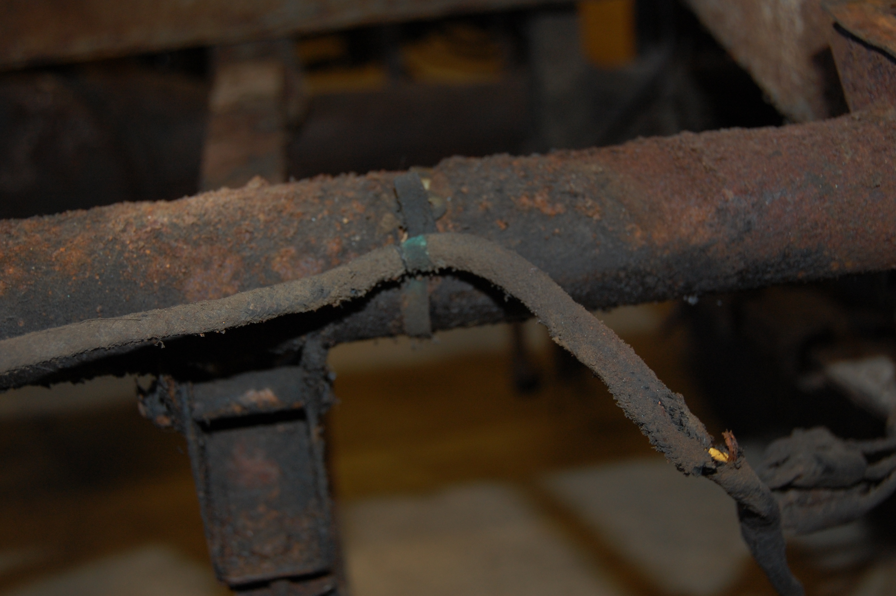
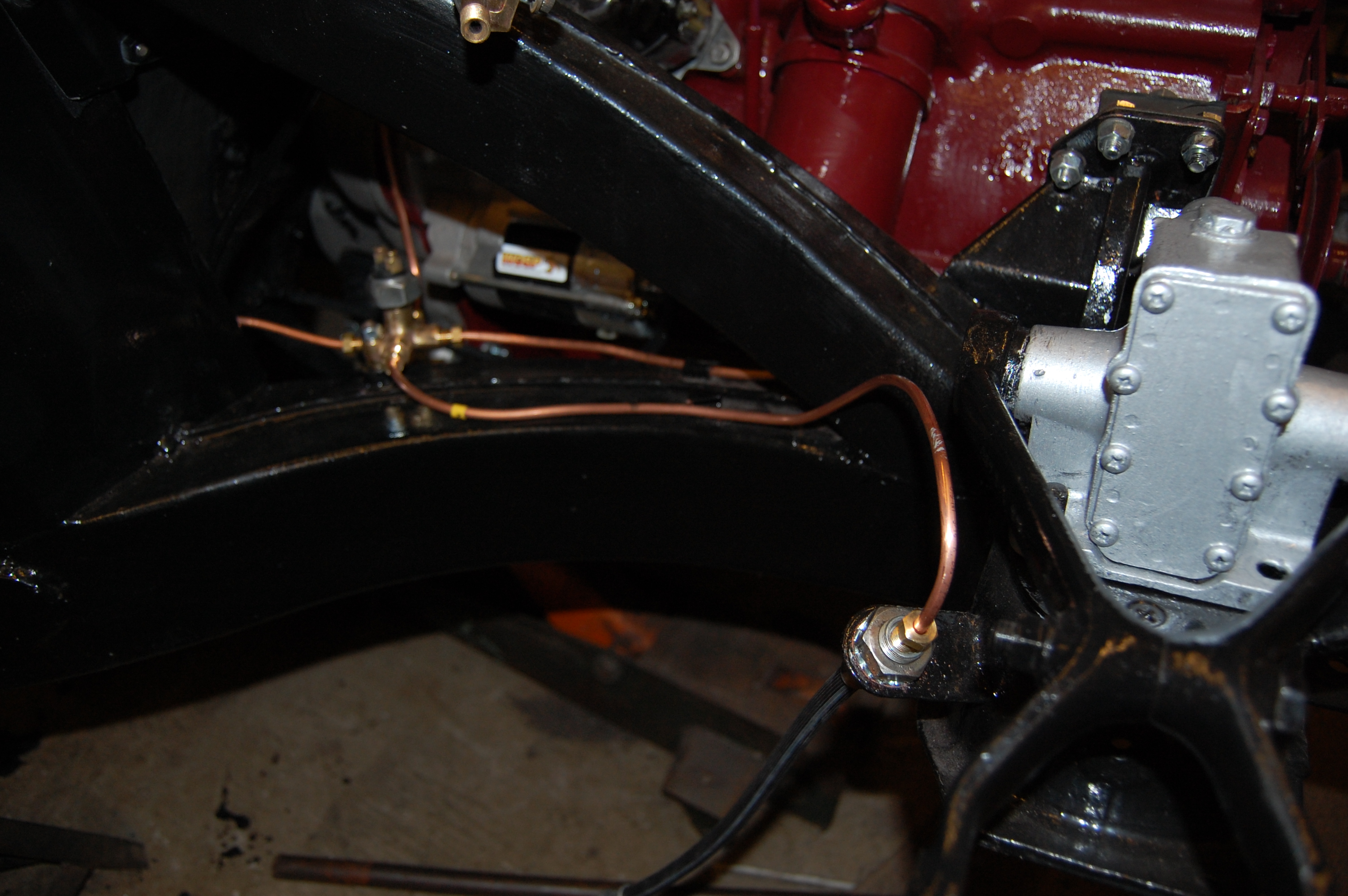
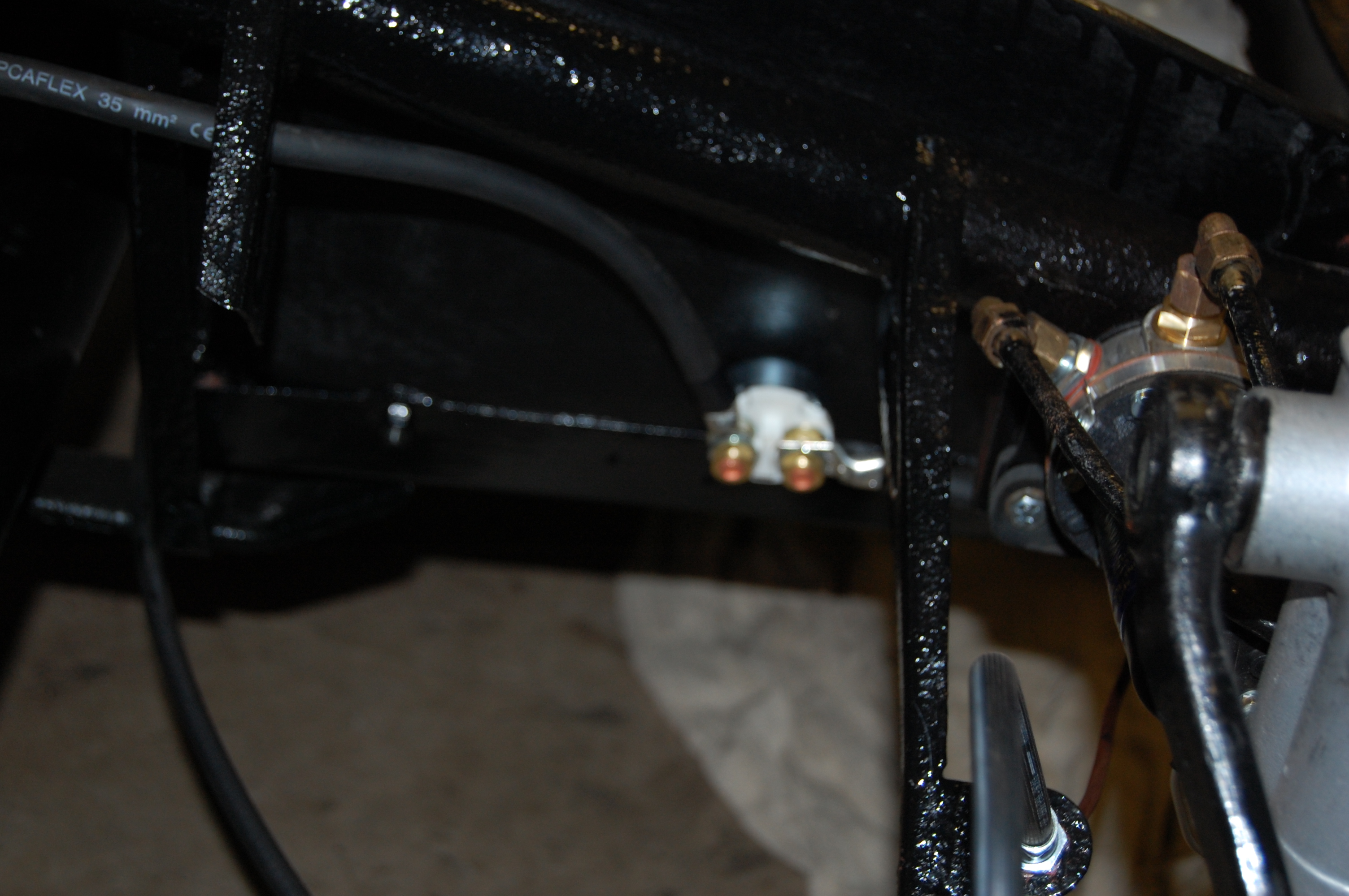
Of note here is the position of the rear brake flexible pipe from the battery carrier union to the two-way union where the pipes are split left to right, the right-hand pipe looping over the differential.
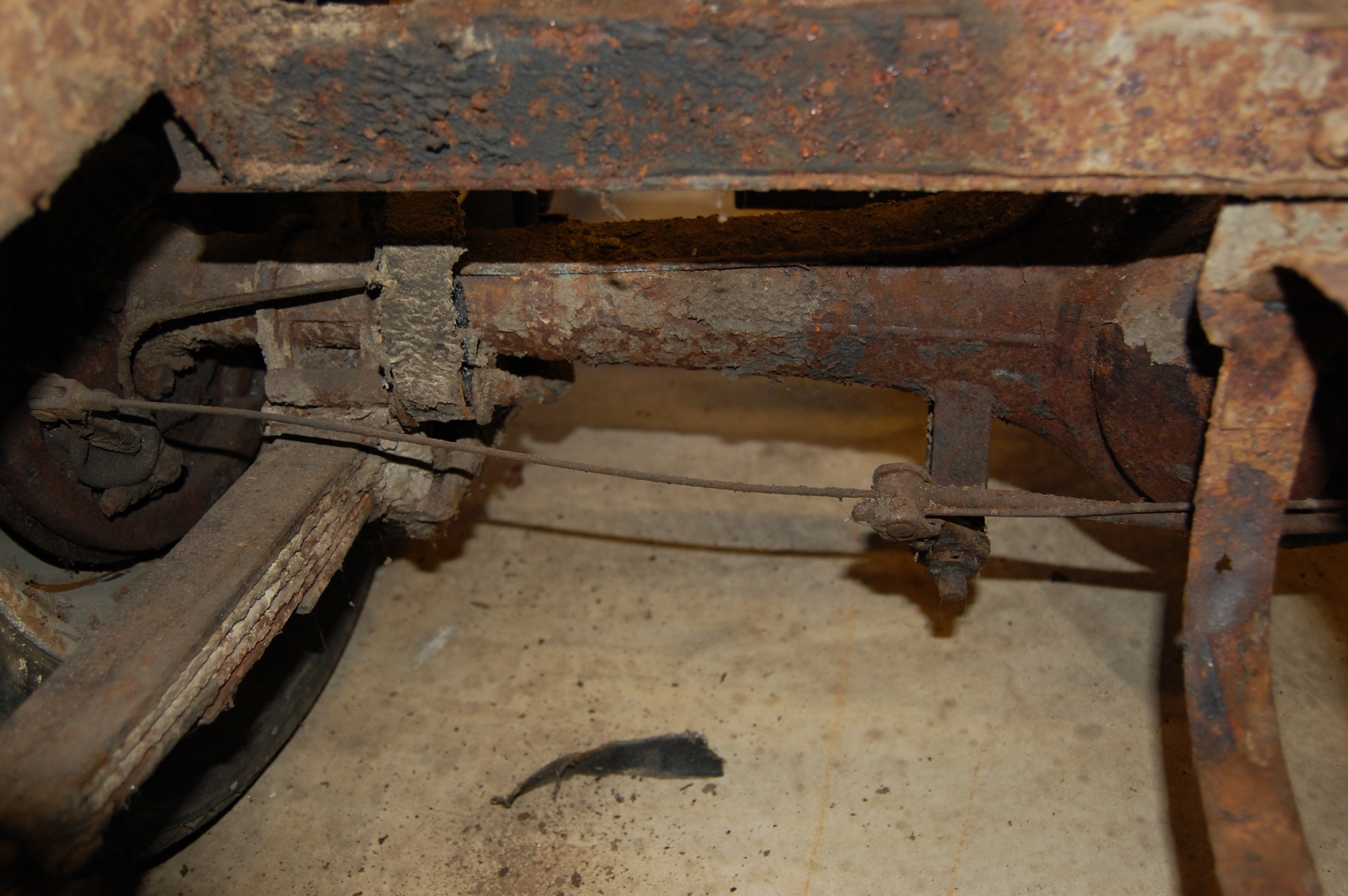
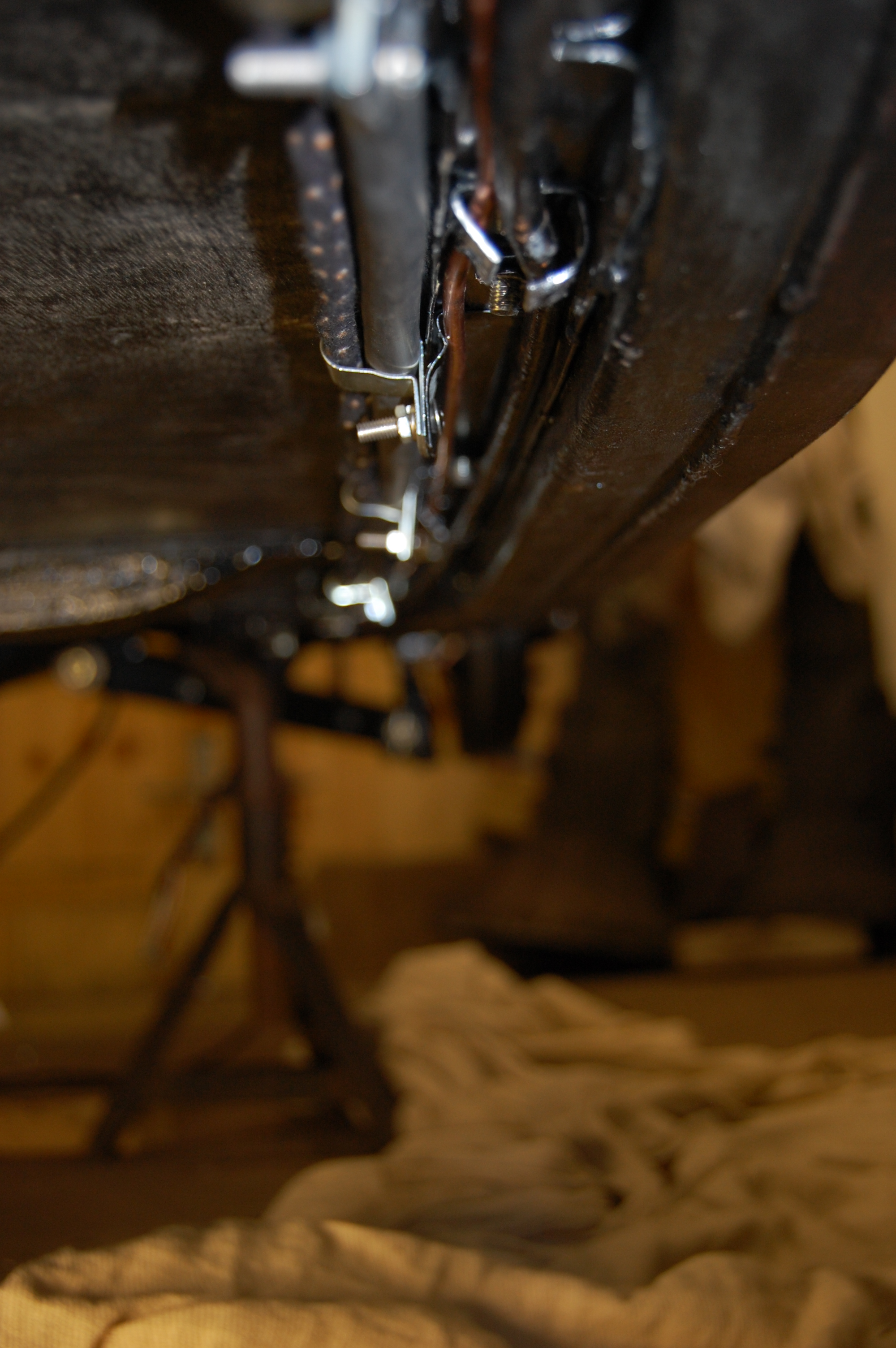
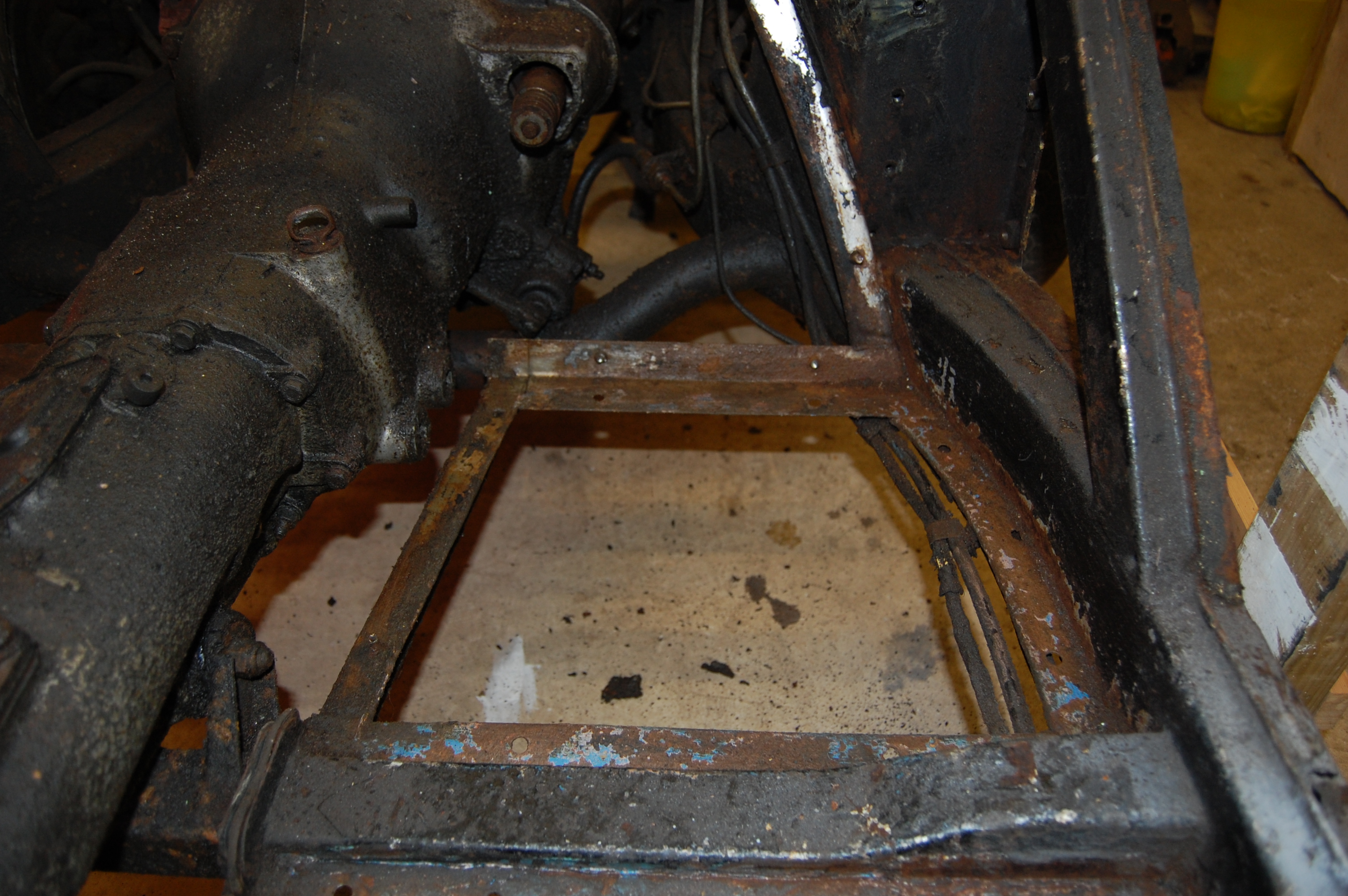
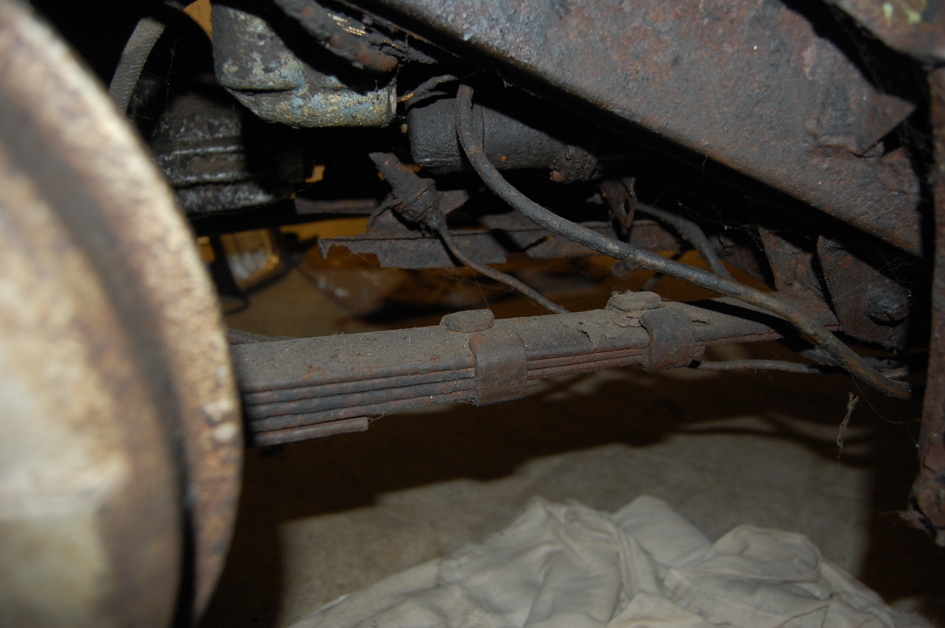
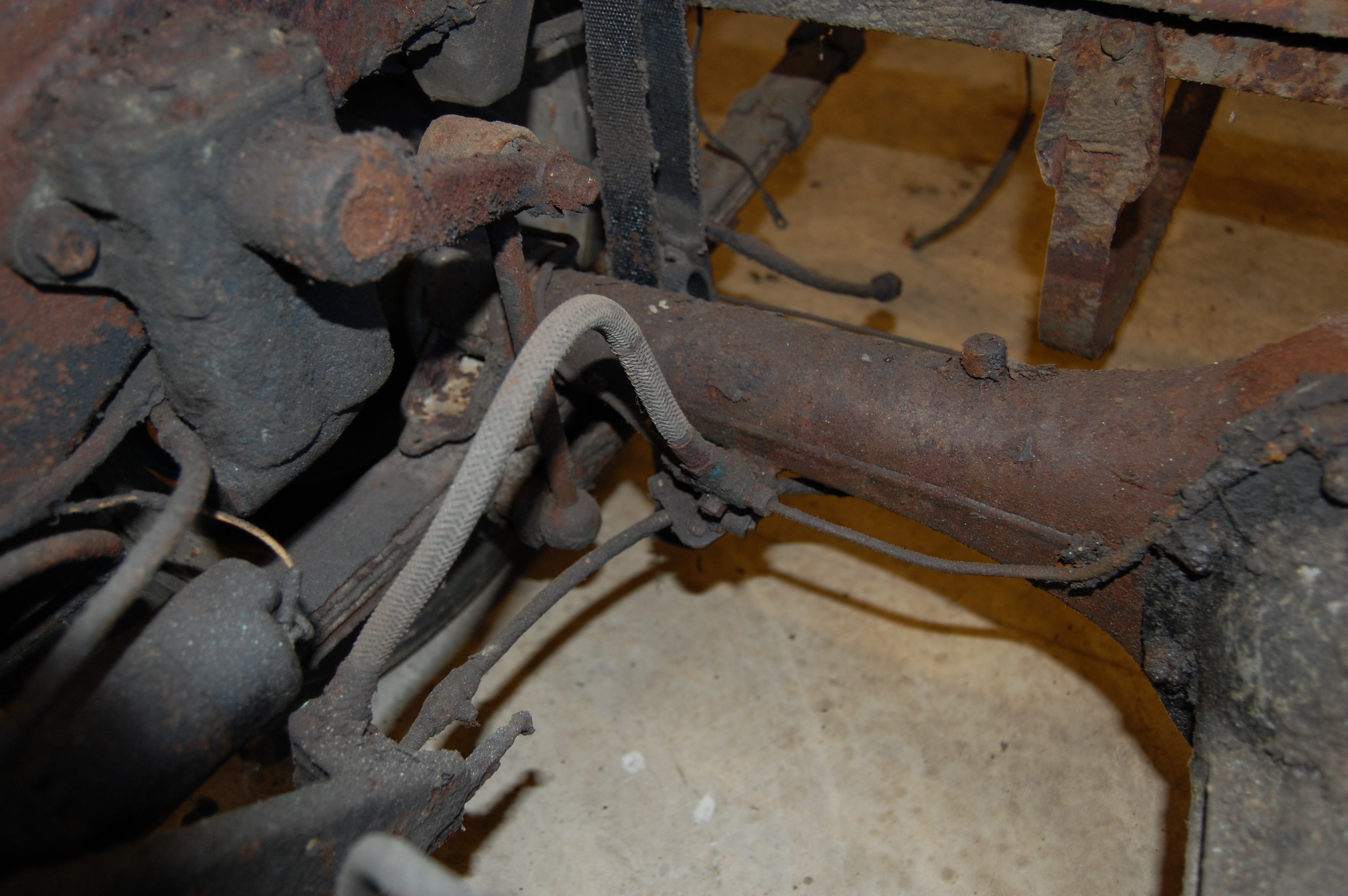
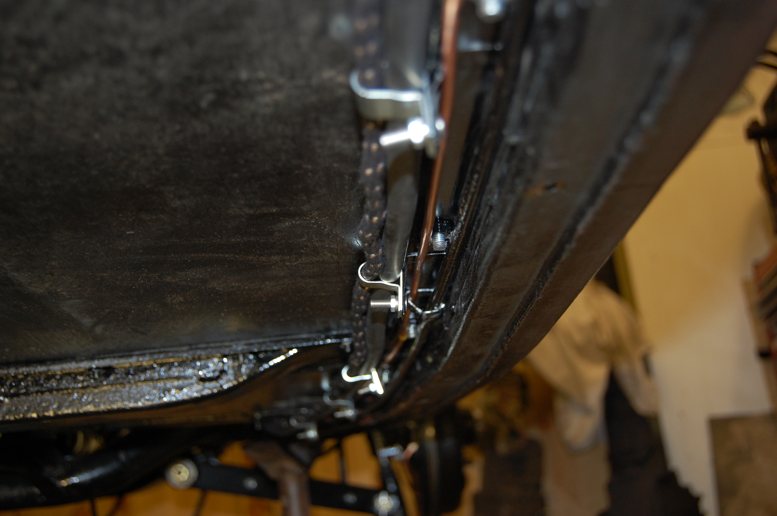
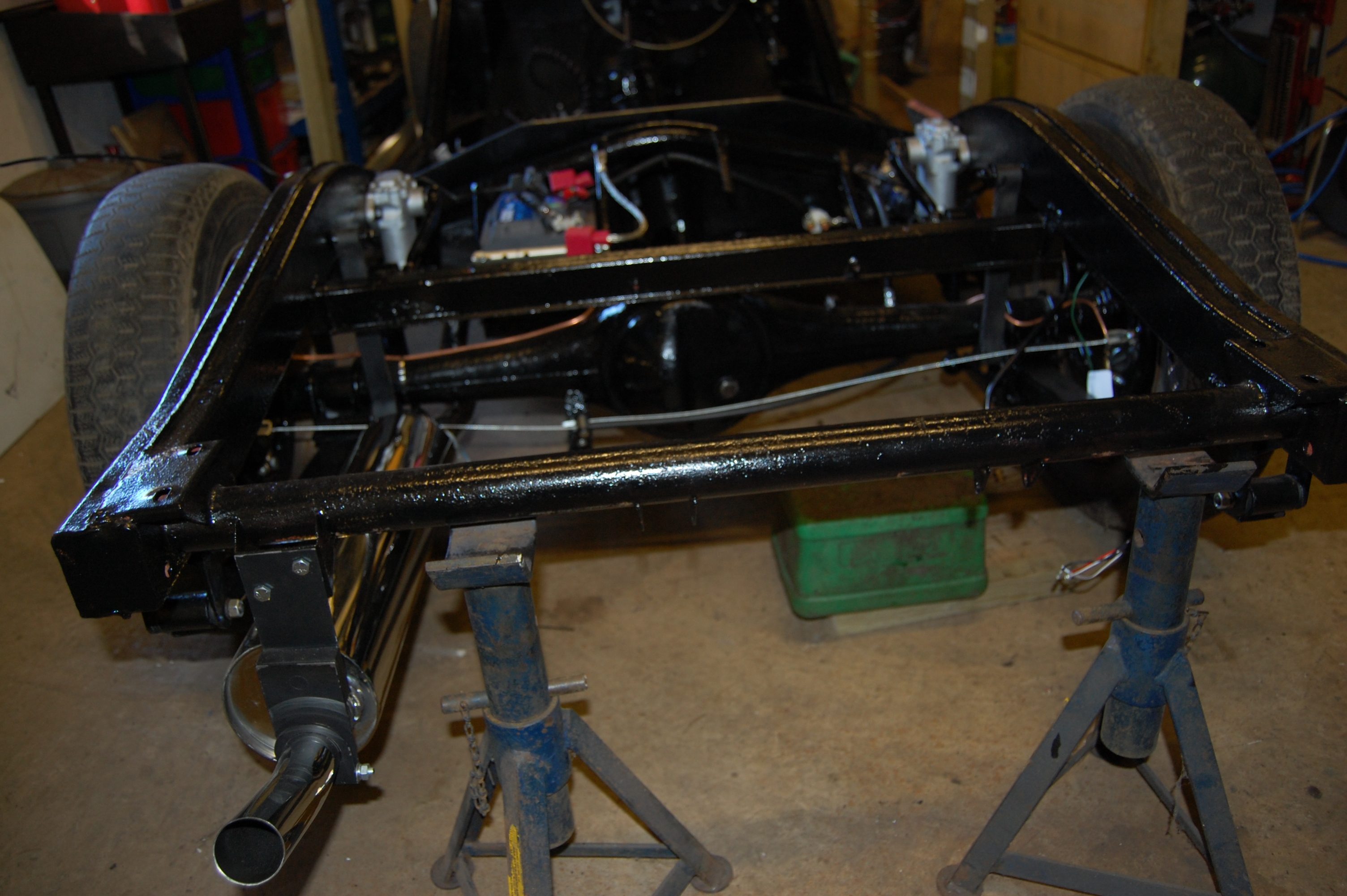
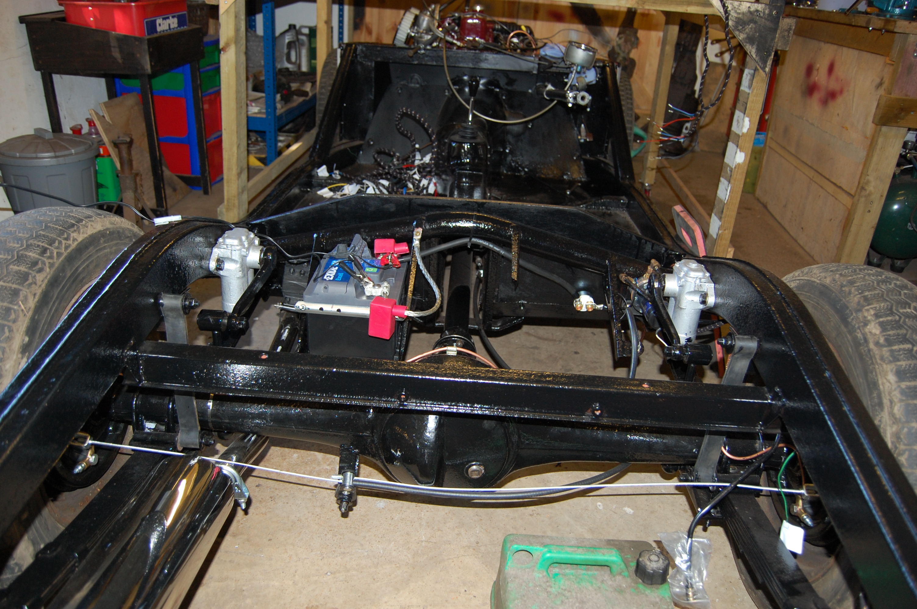
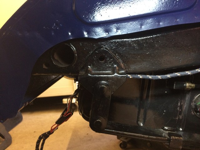
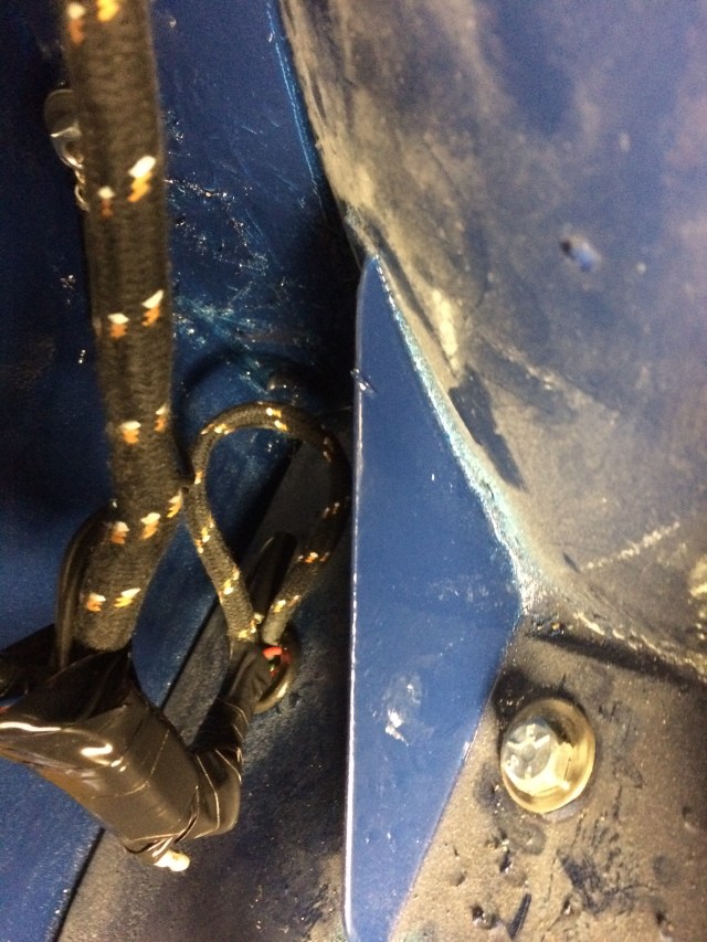
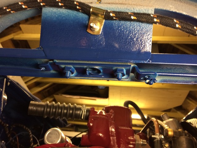
From the rear of the chassis the battery cable and side loom share the same ‘p’ clips mounted on vertical tabs attached to the floorboard rails. the main brake pipe front to rear and the fuel pipe share the parallel route between the floorboard rails and the chassis side (clip needs tightening!)

The retaining clips for the fuel and brake lines are in the form of tabs attached to the outer floorboard rail and are simply bent into position once the lines are in place.
Battery lead and loom secured in ‘P’ clips that bolt to tabs welded to the chassis.
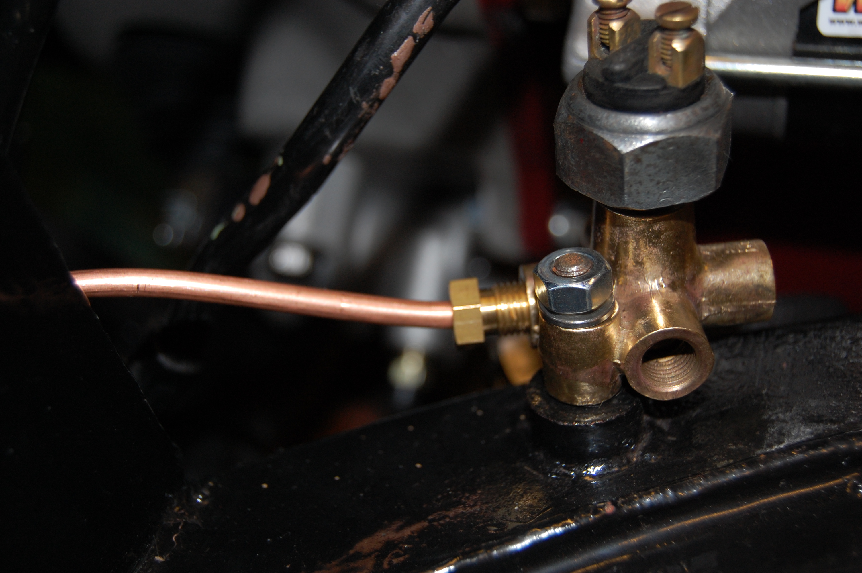
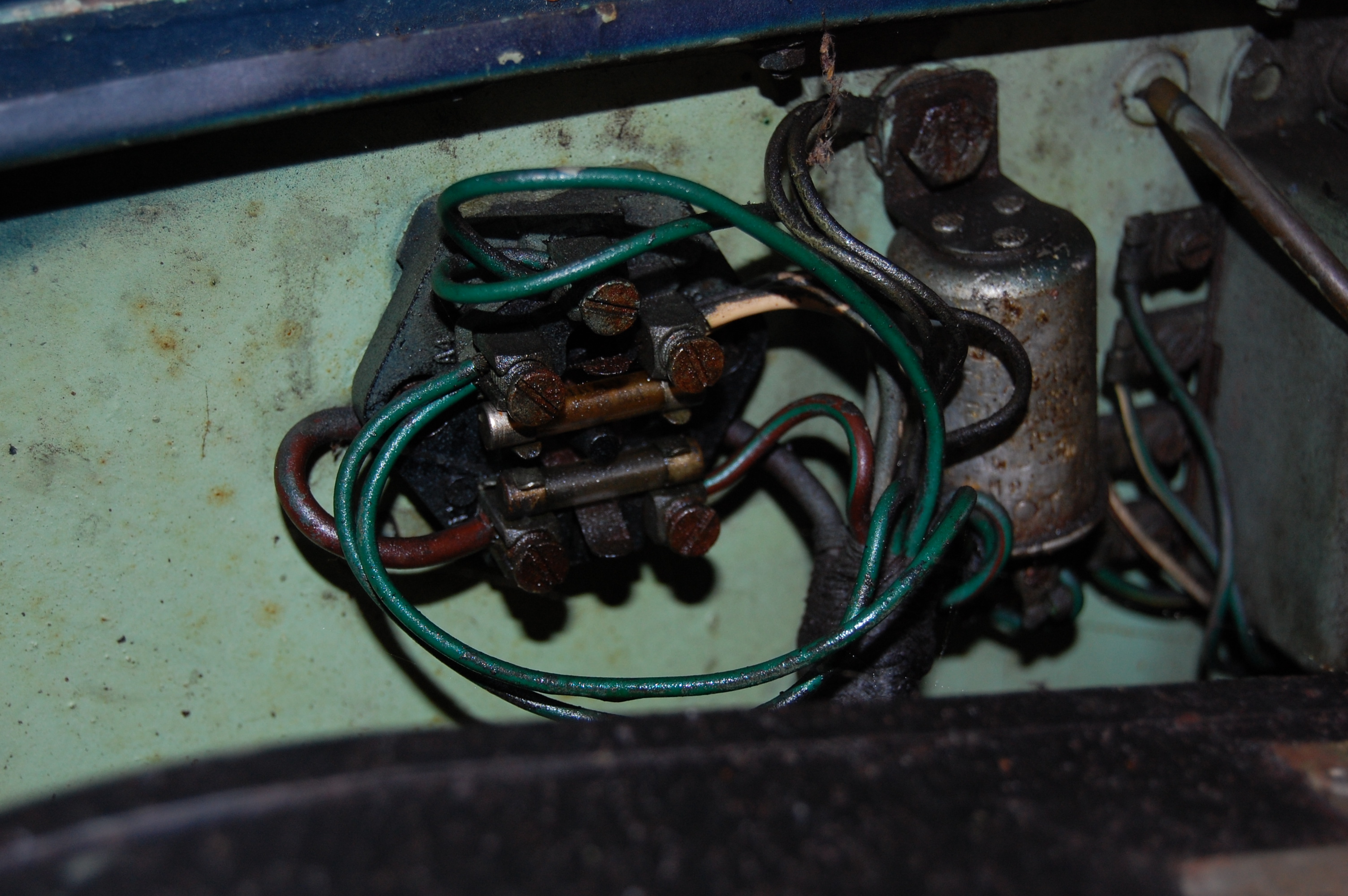
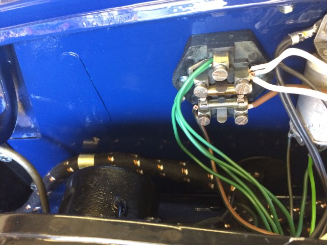
Three-way union and brake light switch mounted on the chassis to the right and forward of the chassis goal-posts. this is the original one cleaned up.
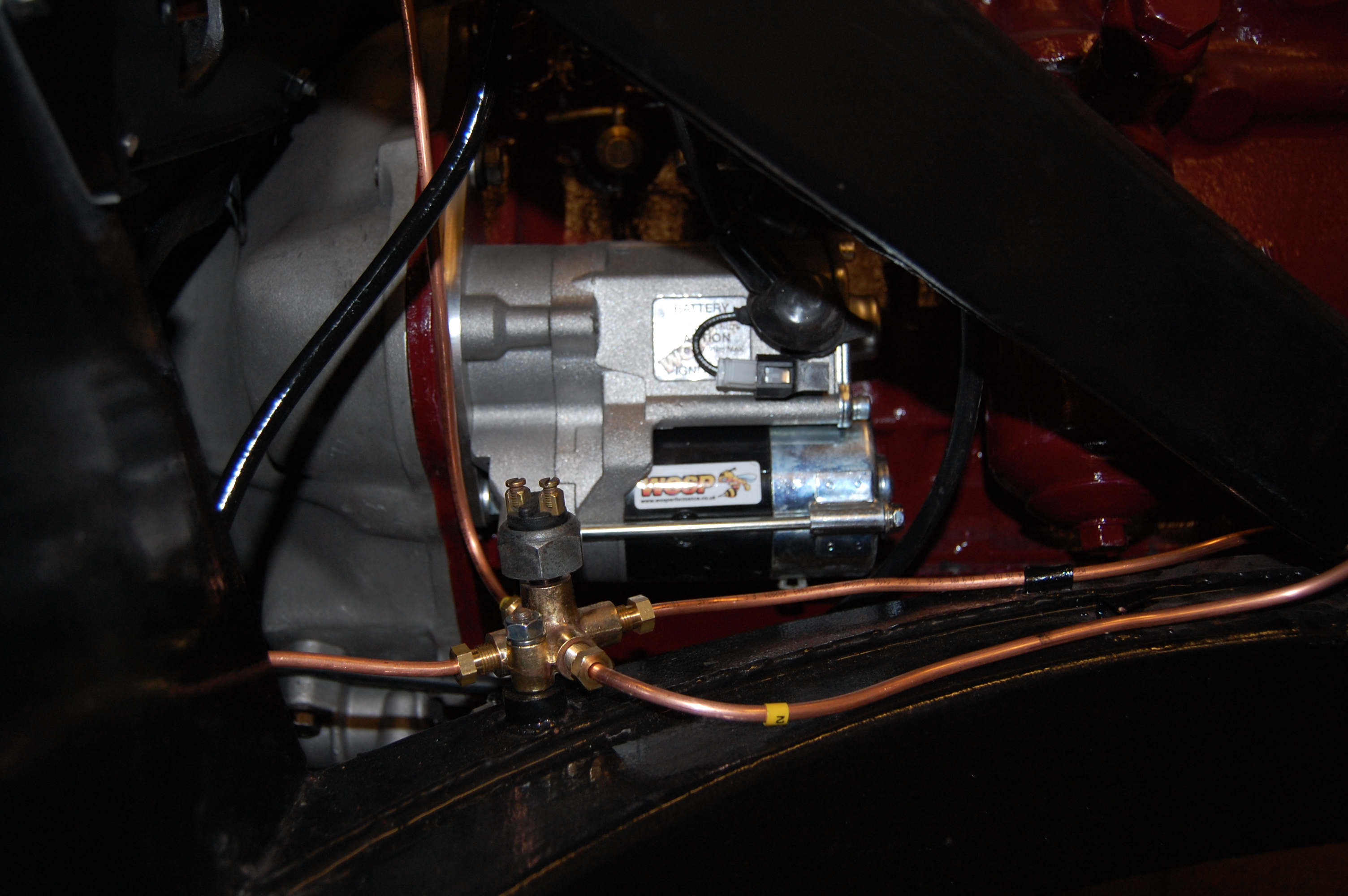
In this shot is the new Wosp hi-torque starter that is a worthwhile upgrade.
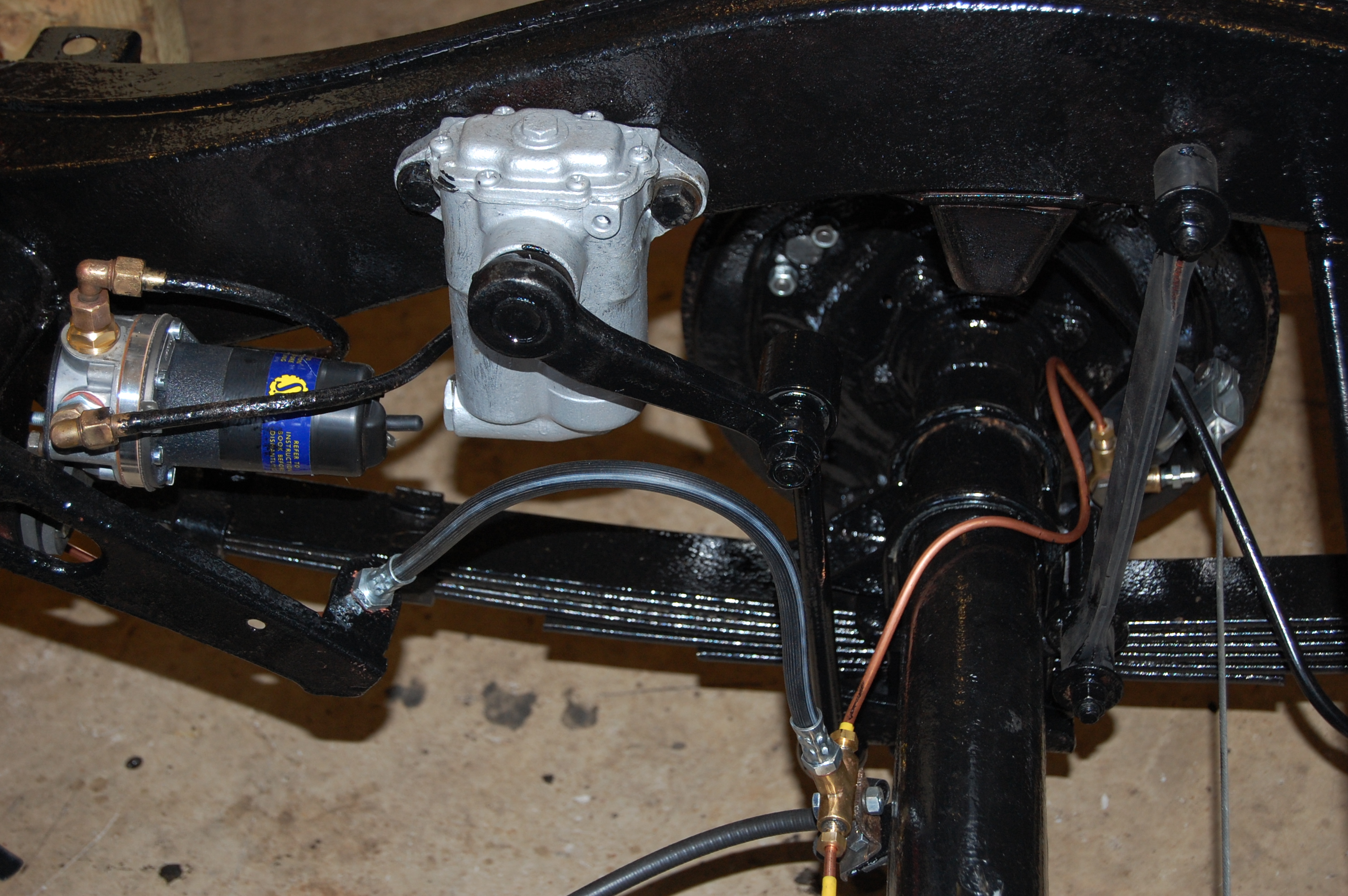
MGA 1500 Rear axle
I added in a battery isolation switch, fitted in-line on the main battery cable.
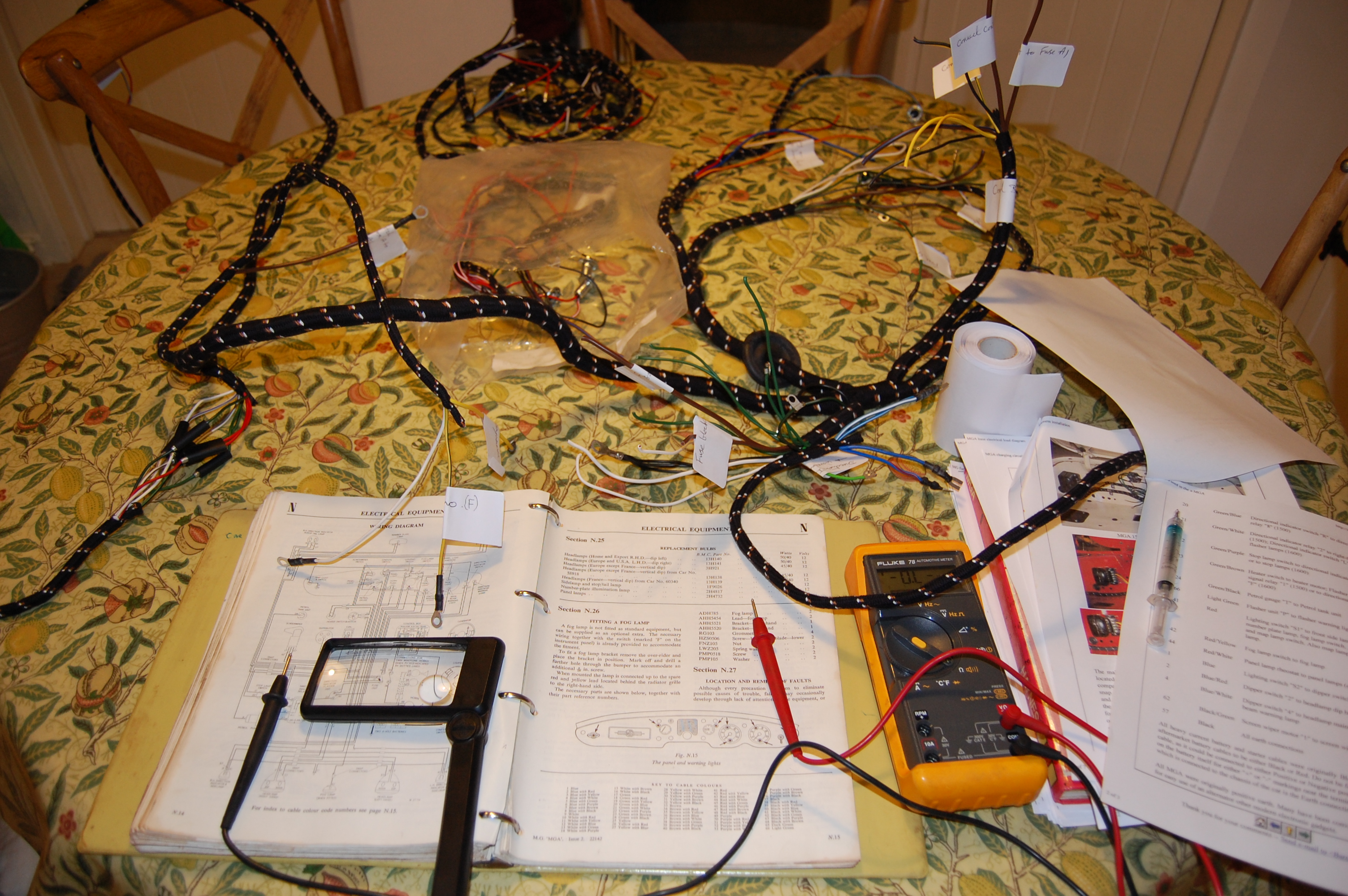
Winter indoor work…marking up the wiring loom. MGA 1500 wiring loom.
There are several points in the loom where sub looms are connected by bullet connectors. In every case, I slathered the male and female connectors with electrical silicon grease and then wrapped in black insulation tape. I’m not that bothered how it looks, but don’t want to be faced with problems of poor connection at some later stage. I’ve since revisited connectors that are exposed and replaced tape with heat shrunk insulation.
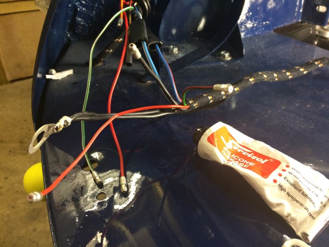
This is particularly important where the rear loom extension joins the main side loom, as this is very exposed to road dirt and water and also the front extensions to the side and head lights.
The control box is now only a junction box as I’ve fitted an alternator.
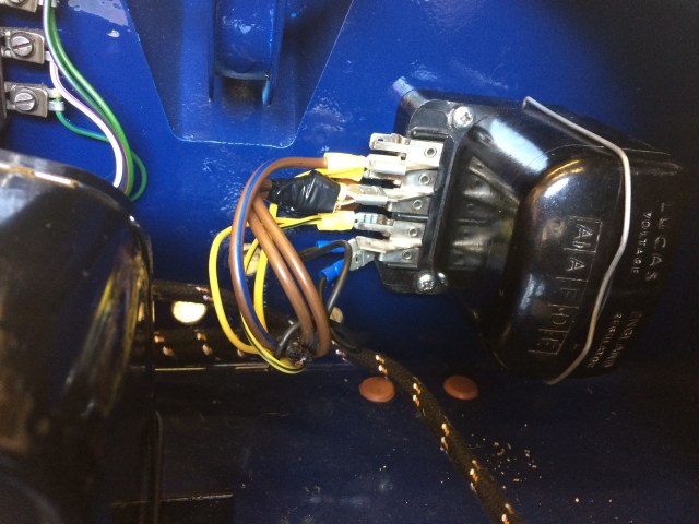
The wires into the fuse block were eventually tidied up a bit!
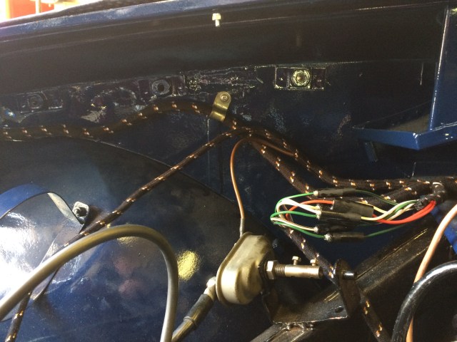
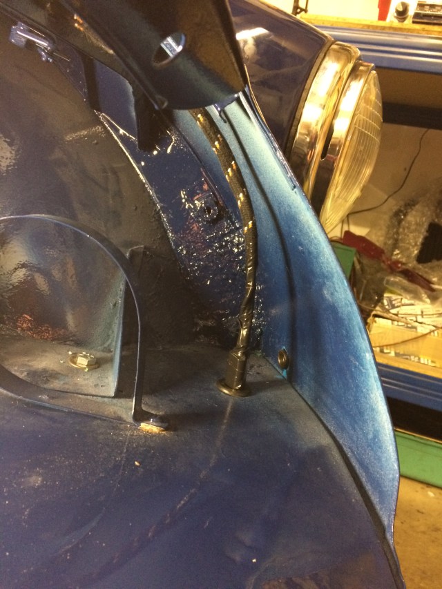
The picture below shows the greased and bundled connectors where the side loom splits to the horn wires and side/headlamps. Also shows where the paint didn’t reach!
Note the earth lead connected to the elongated wing/fender bolt as was original, also that the fog lamp connector which is unused, is exposed – since insulated with a female bullet connector.
Bill Jeffries – billnjeffries@gmail.com

Thanks for tis information