This section includes the various changes and alterations that I’ve made, which have seemed sensible to me and particularly aimed at creating a car that’s as near to original as possible, but suited to driving distances in modern traffic. These will be added as and when the job is completed.
These include:
- Five speed gearbox conversion
- Dynamo to alternator (Dynamator) conversion
- Hi-torque starter
- Electronic ignition
- 12 volt single battery conversion
- Under floor exhaust heat shield
- Seat Belts
- Twin USB charging port
- Sun Visors
- LED third brake lamp.
- Period Tourist Trophy Steering Wheel
- Upgraded Rear Indicators
- Hazard Warning Lights
- Polybush Suspension Bushes
- Fire Extinguisher
- Rear Main Drip Catcher
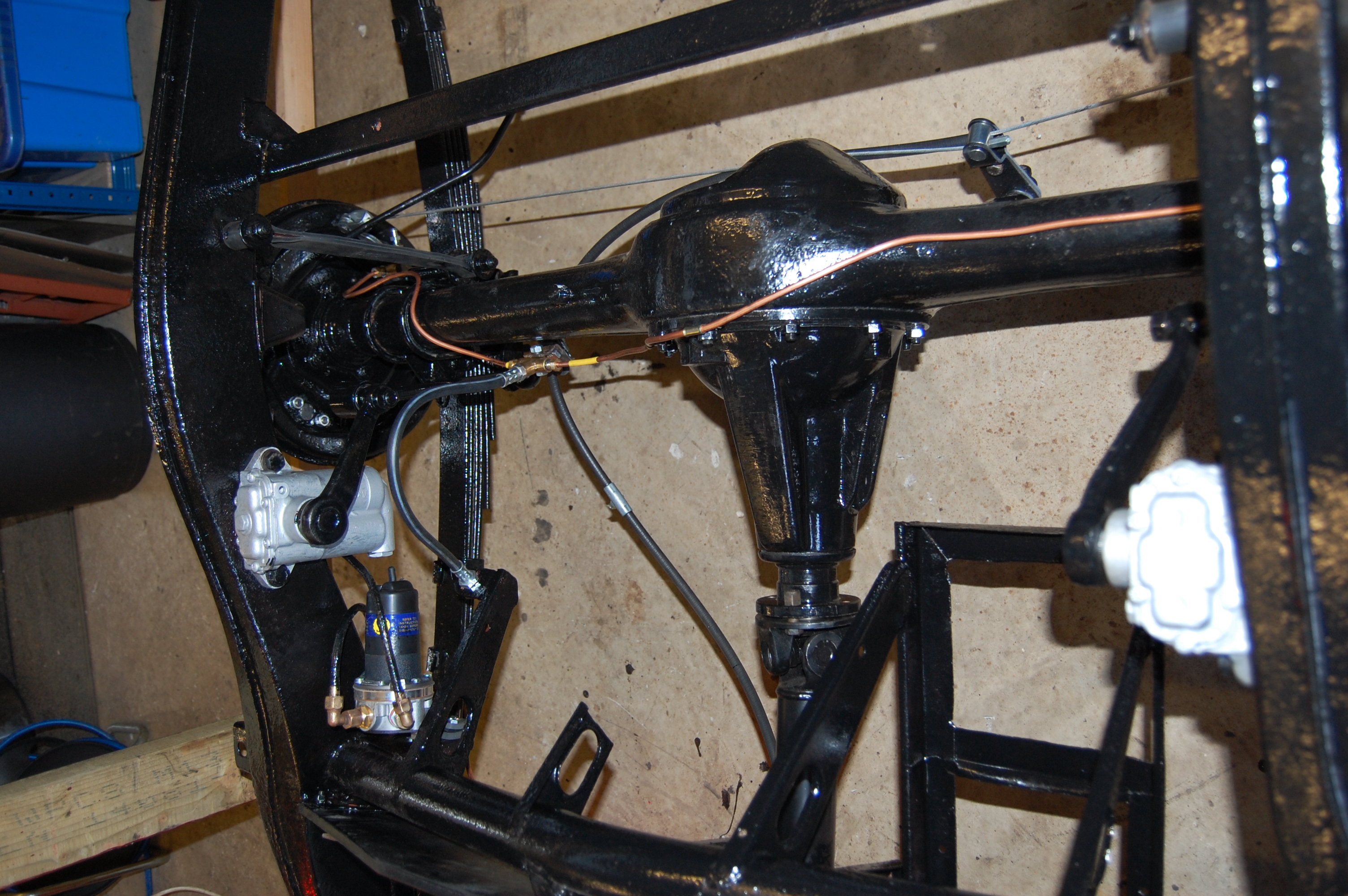
The notable exception here is that I’ve chosen to stick with the original drum brakes, rather than convert to front discs. The reasons for this choice is that the original brakes in good condition, were powerful enough for a standard car used in normal road conditions and partly cost. I’ve fitted all new cylinders, lines, shoes and drums, so we’ll see how it goes.
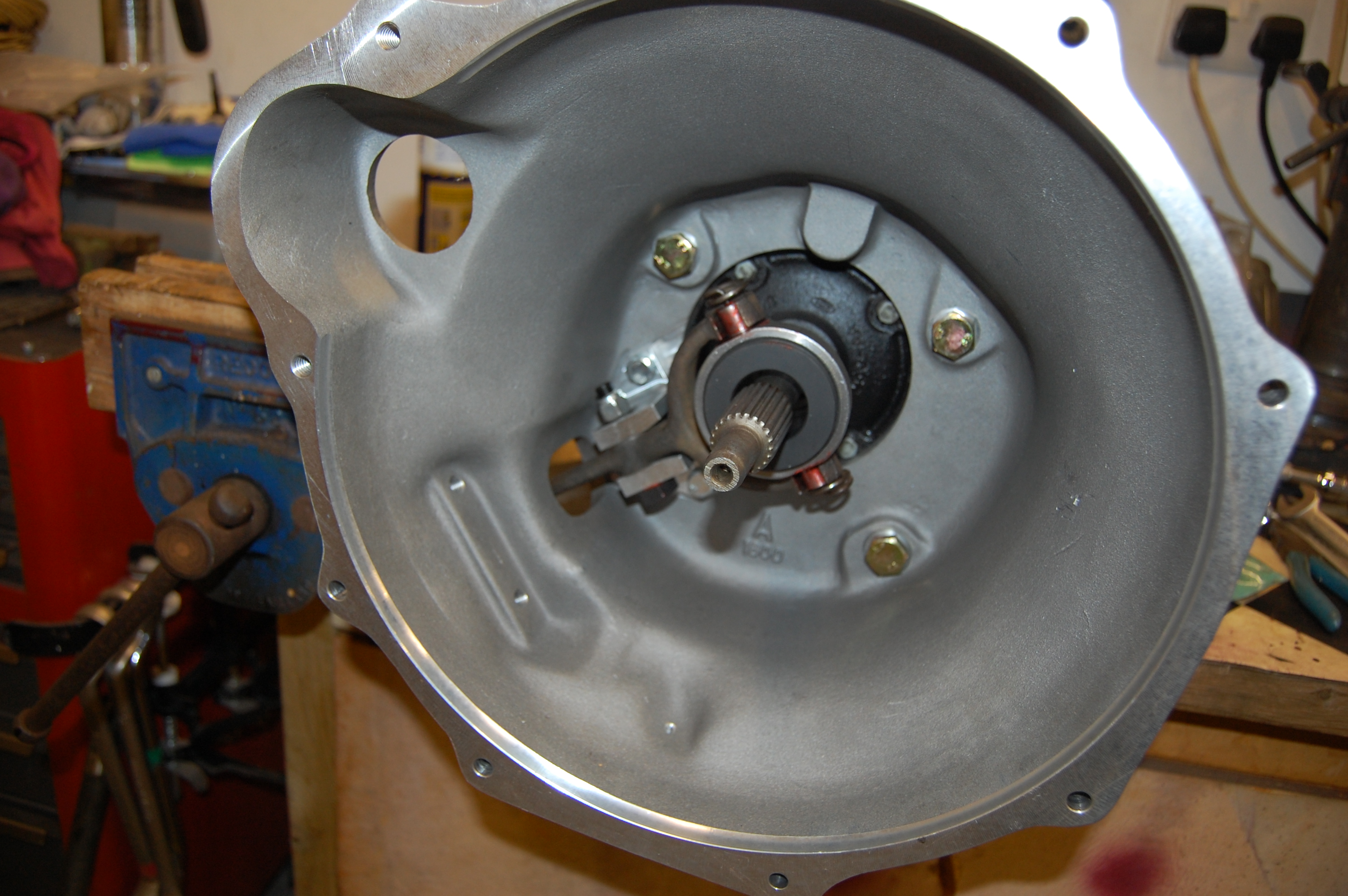
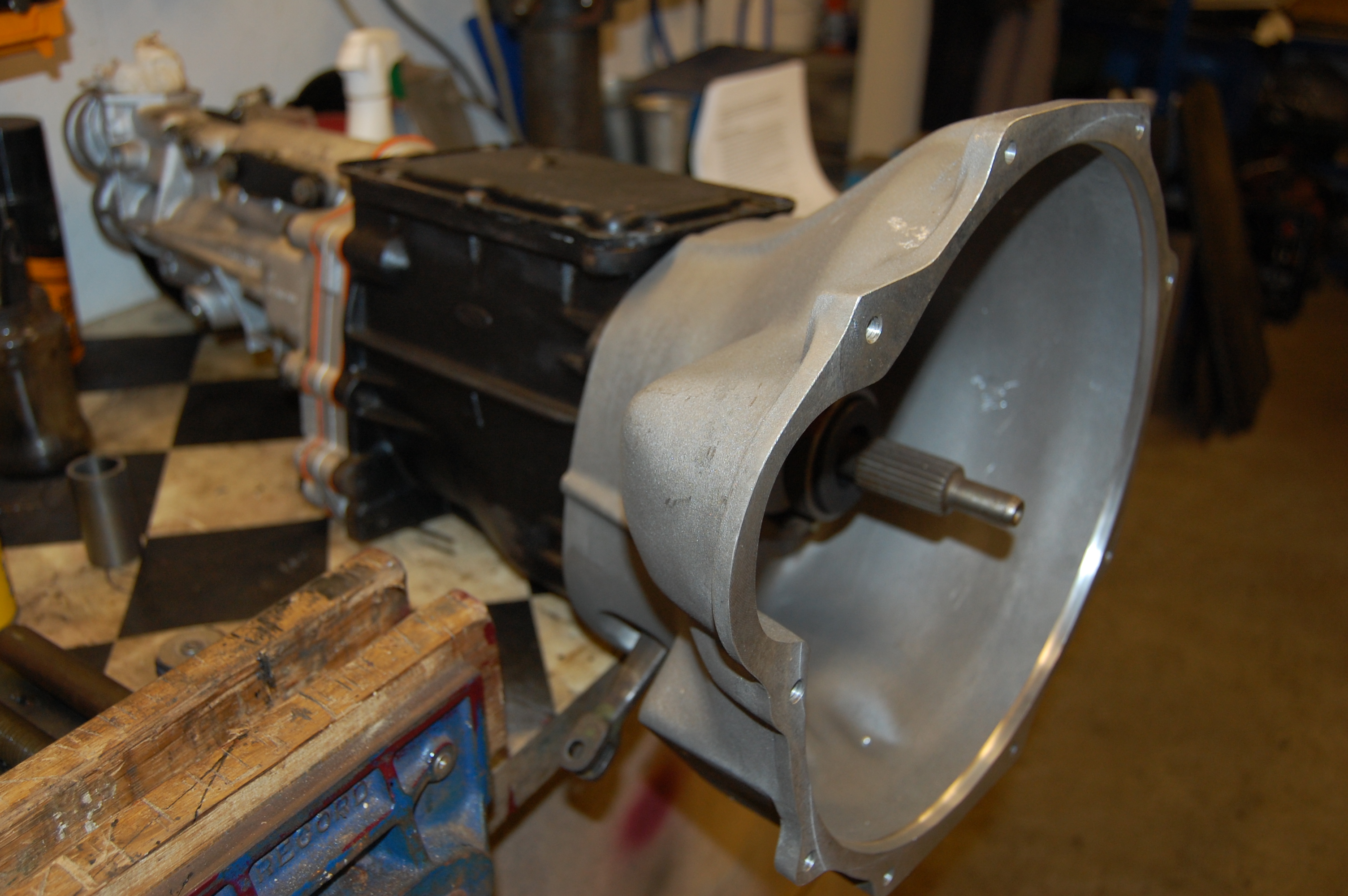
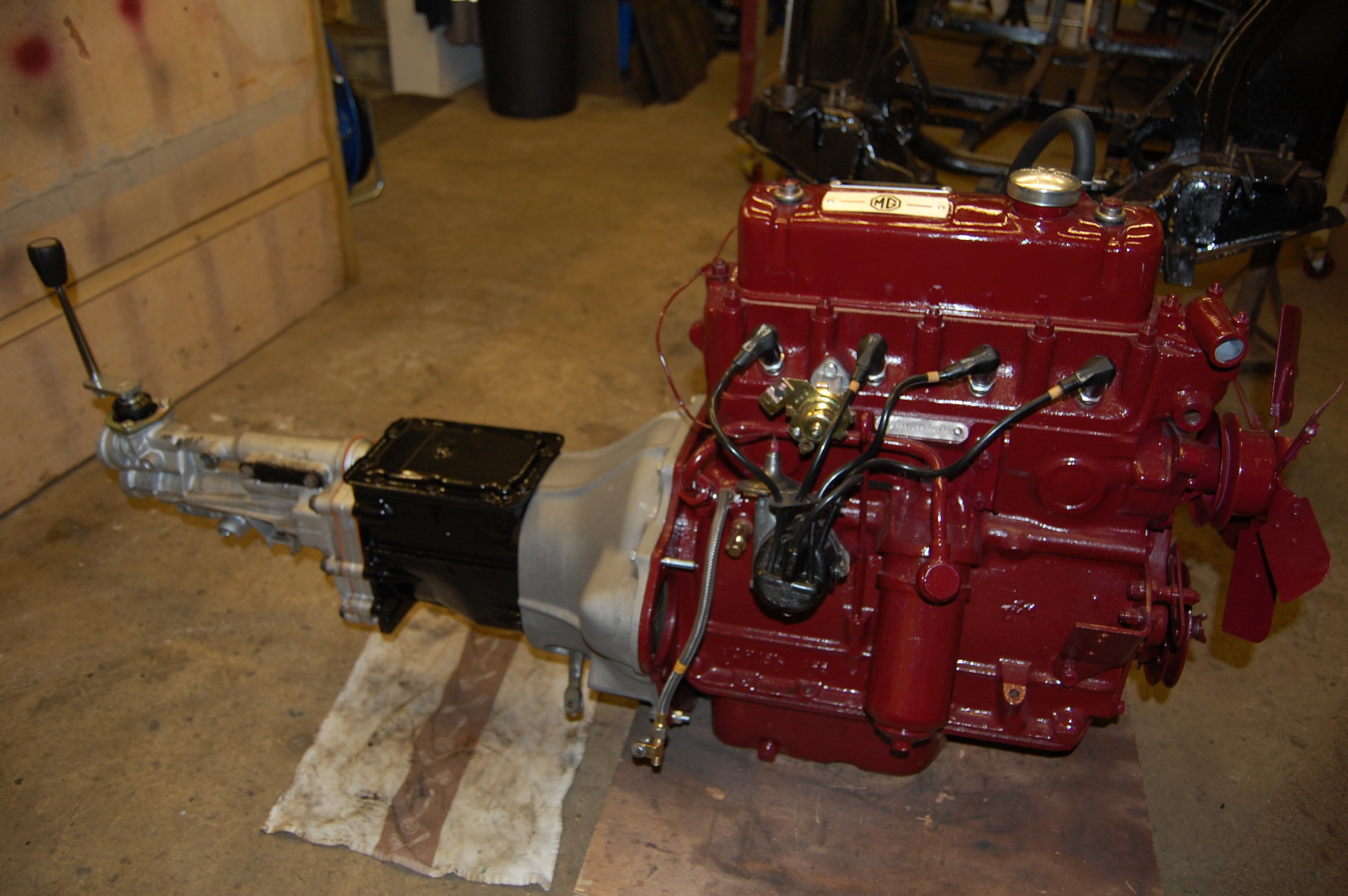
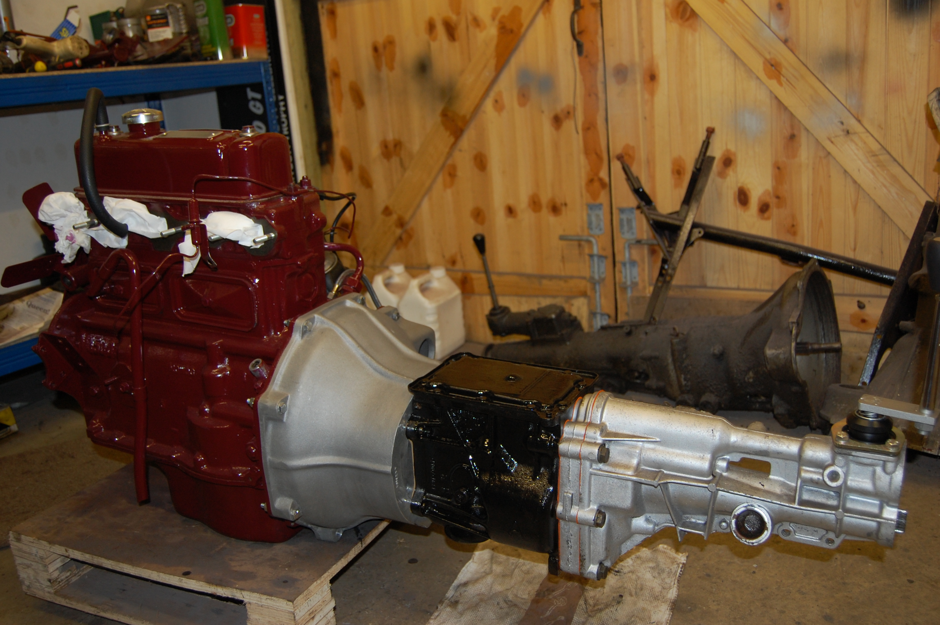
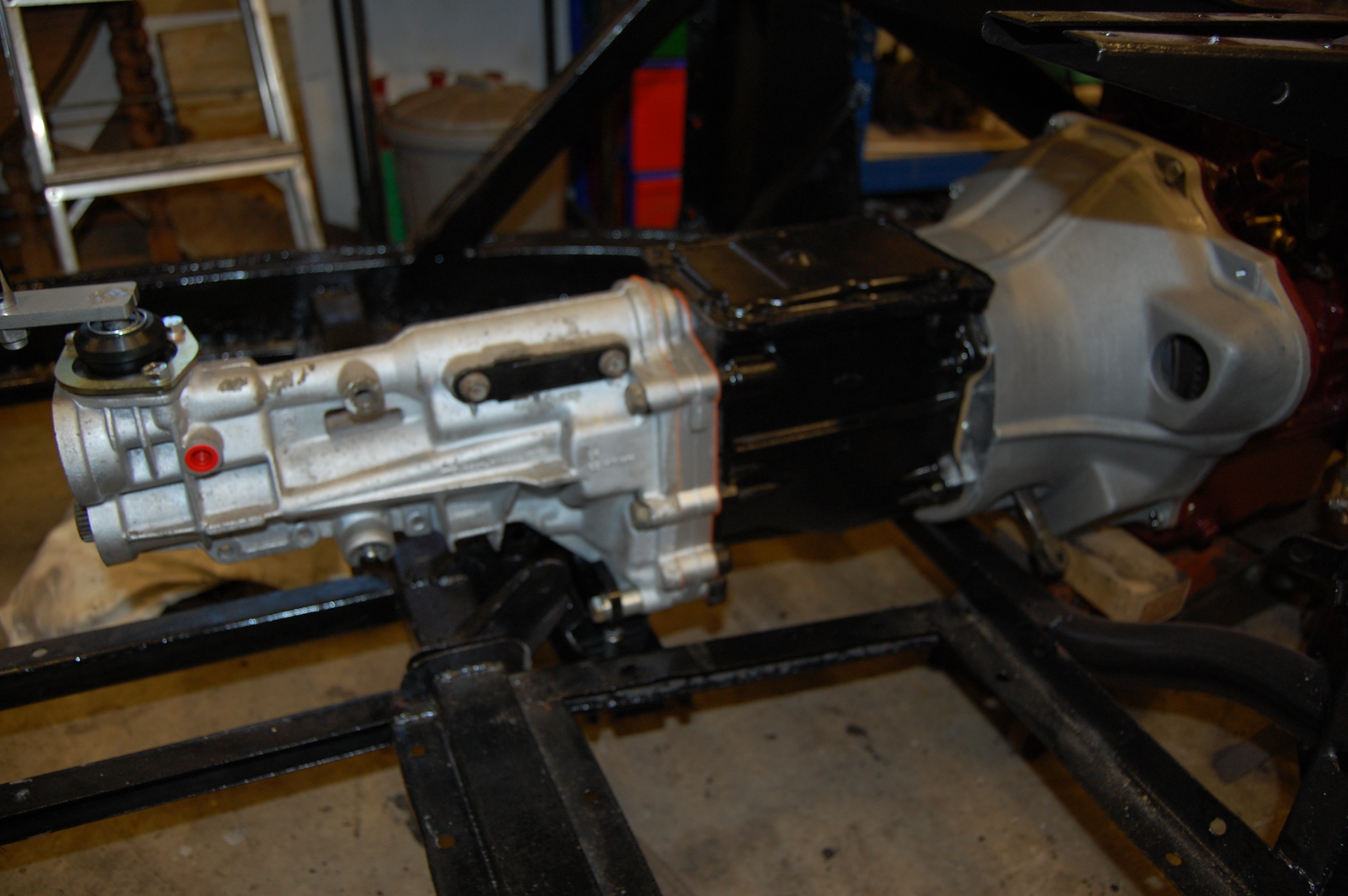
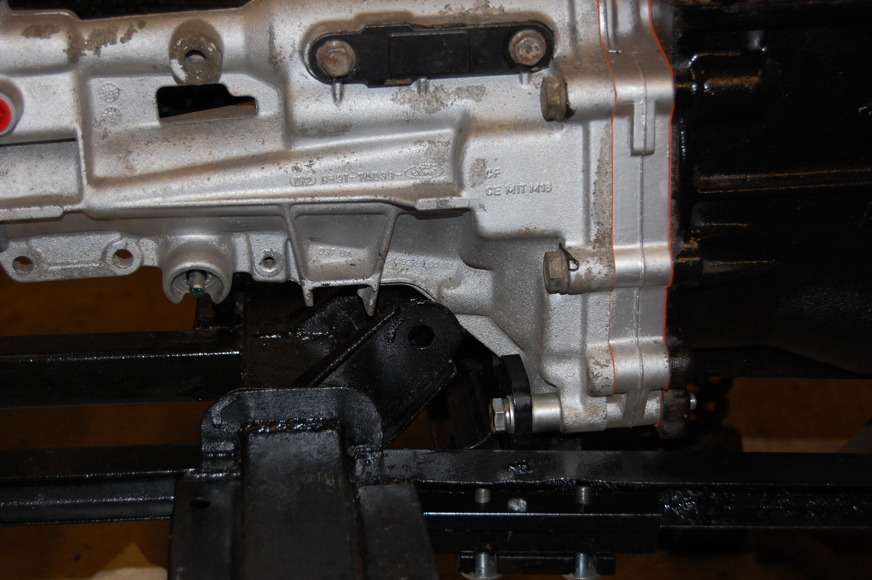
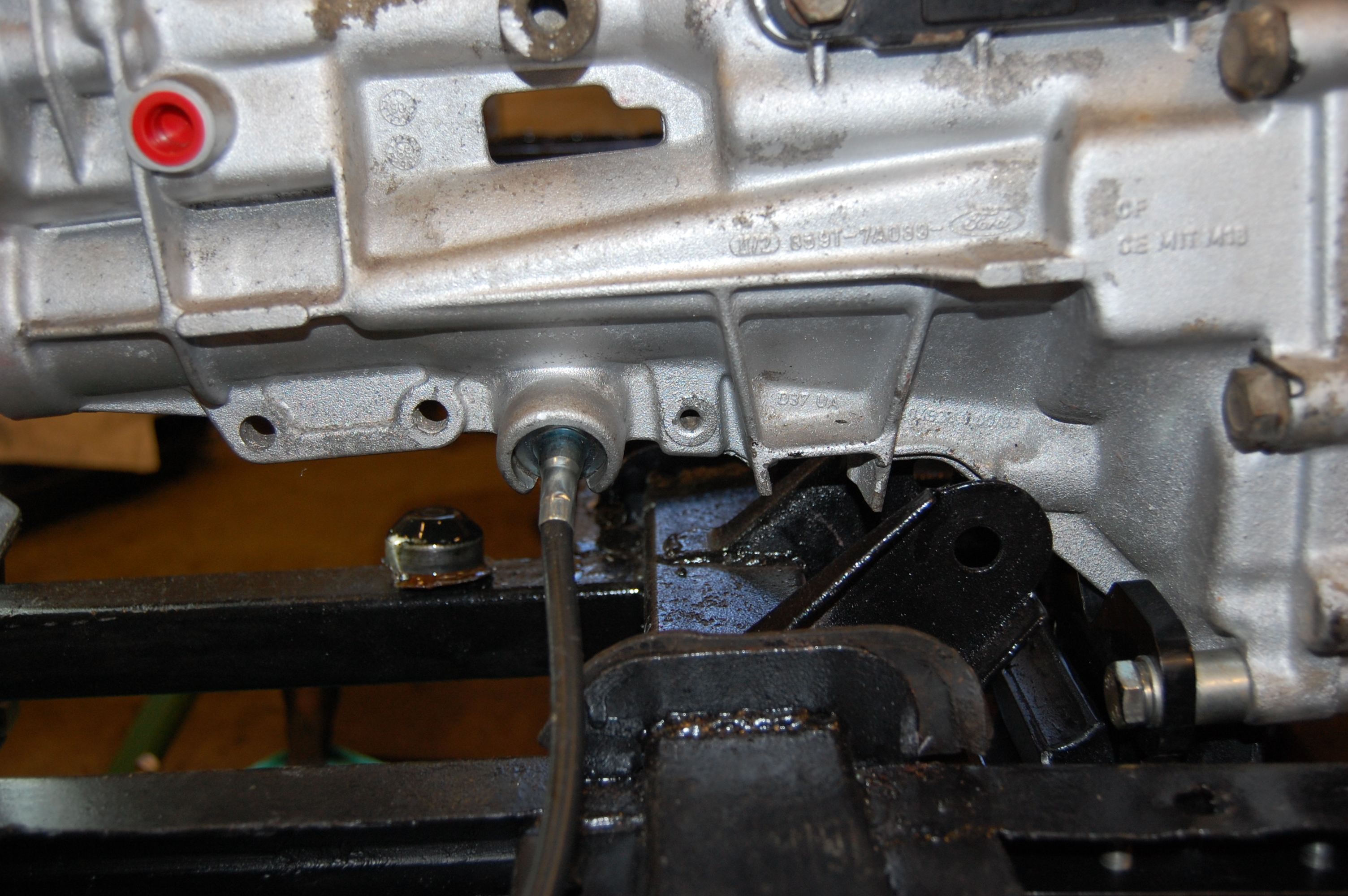
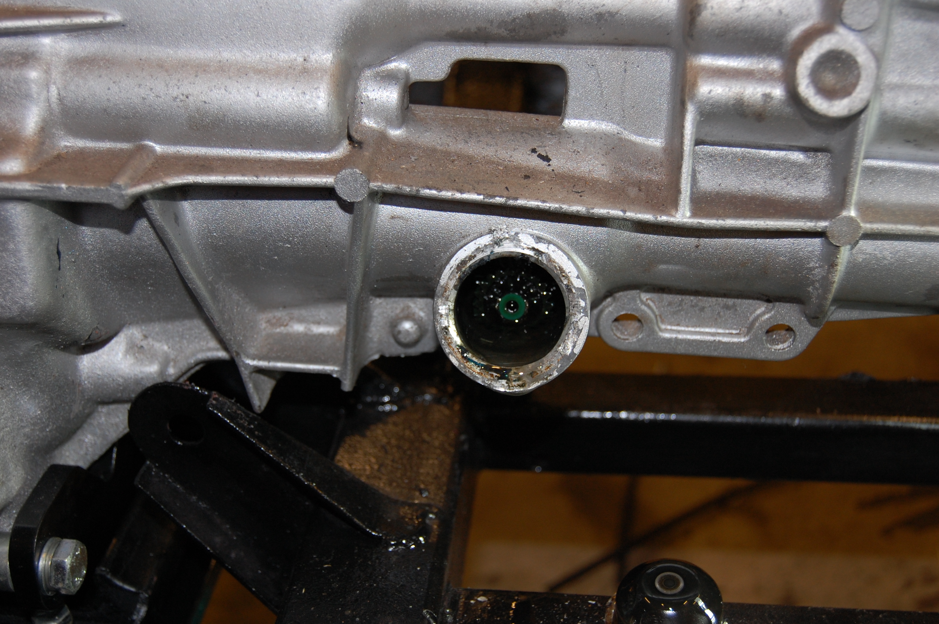
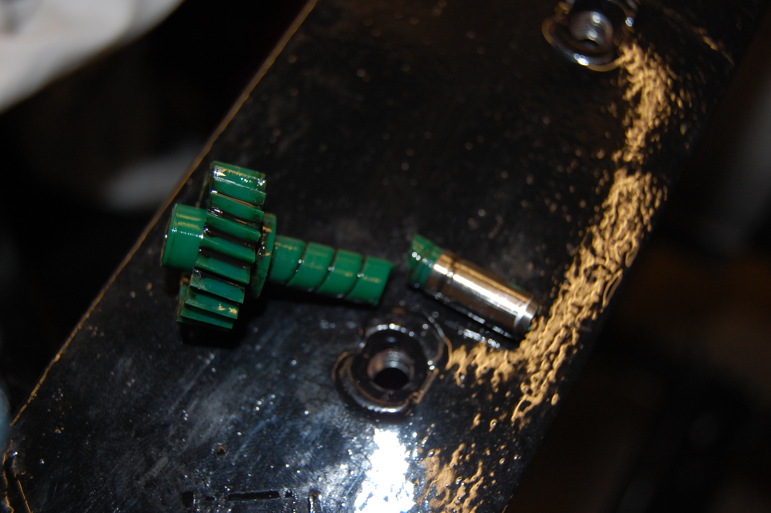
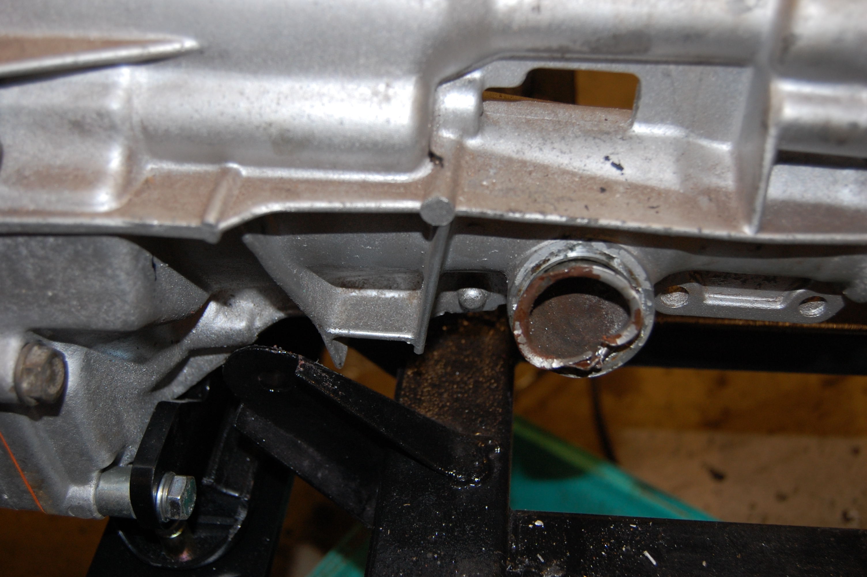
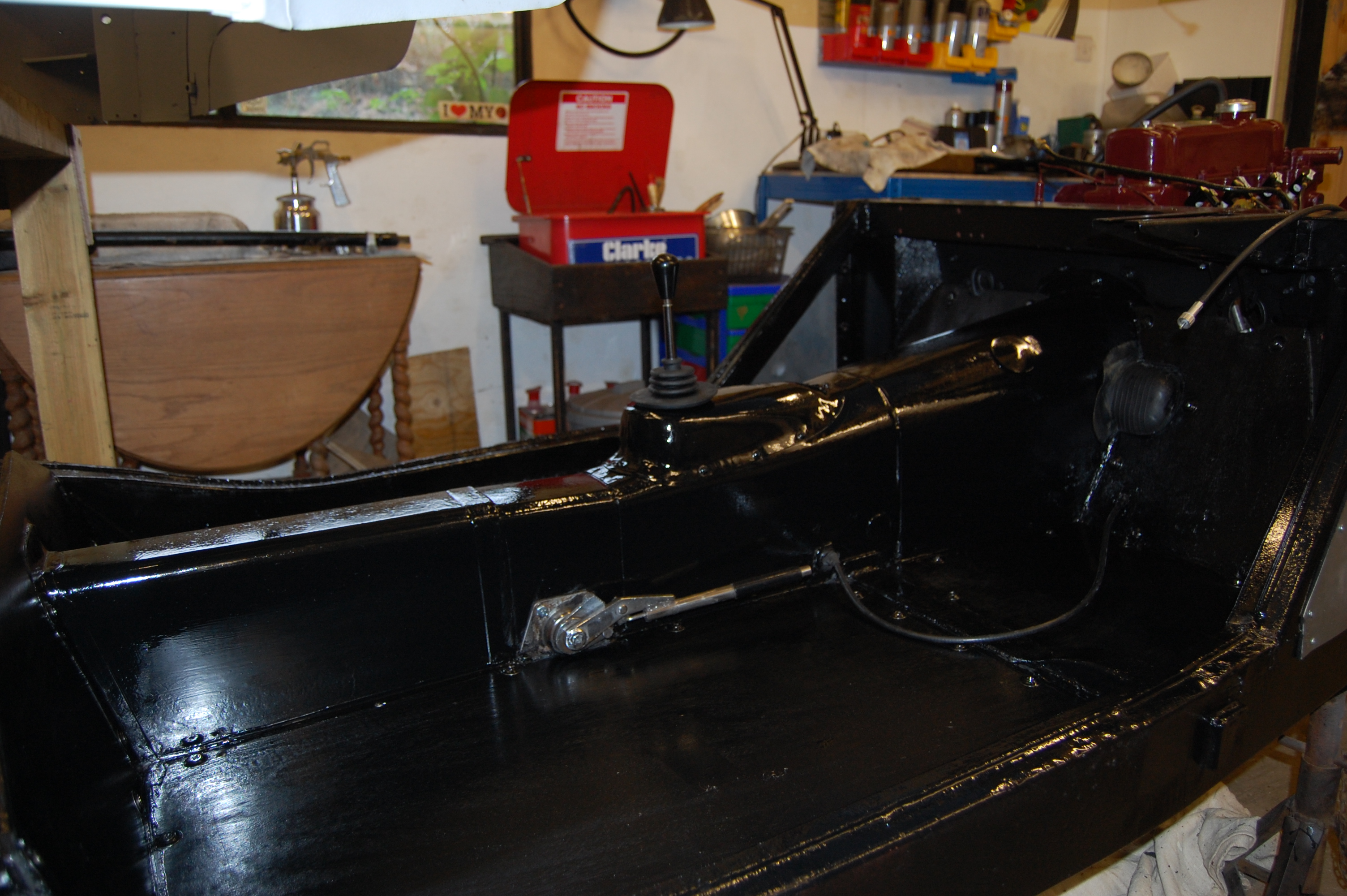
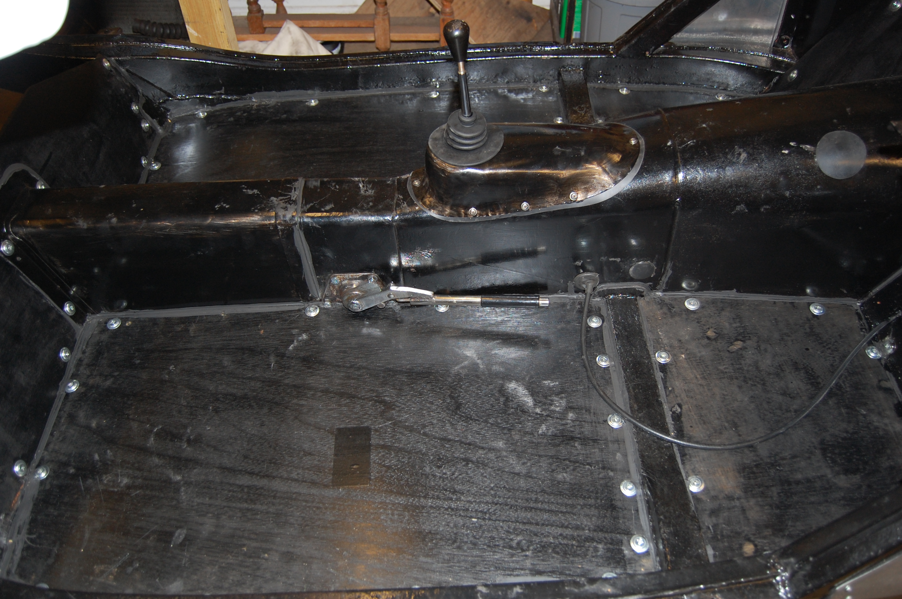
Five speed gearbox conversion.
Of all the conversions and up grades, the 5-speed gearbox conversion is the one that I was convinced of from the start, having listened to friends that had done it and read many positive reviews. The difference that one extra gear makes is enormous – reduced revs, giving relaxed cruising, improved fuel economy, reduced engine wear and reduced emmisions.
The Hi-Gear conversion kit using the Ford Sierra Type 9 gearbox is the best current option and the conversion kit superb, with everything needed and excellent instructions. The Type 9 gearbox is now becoming more difficult to find and as a result prices are going up, so perhaps now the overall cost is becoming more prohibitive. I was fortunate to buy a re-conditioned unit in 2010 at around £350 as from the same supplier now (2022) they are £1000+. There are now alternatives to consider, which were not availaible when I started my restoration, notably the Mazda MX5/Miata.

Dynamo to alternator conversion.
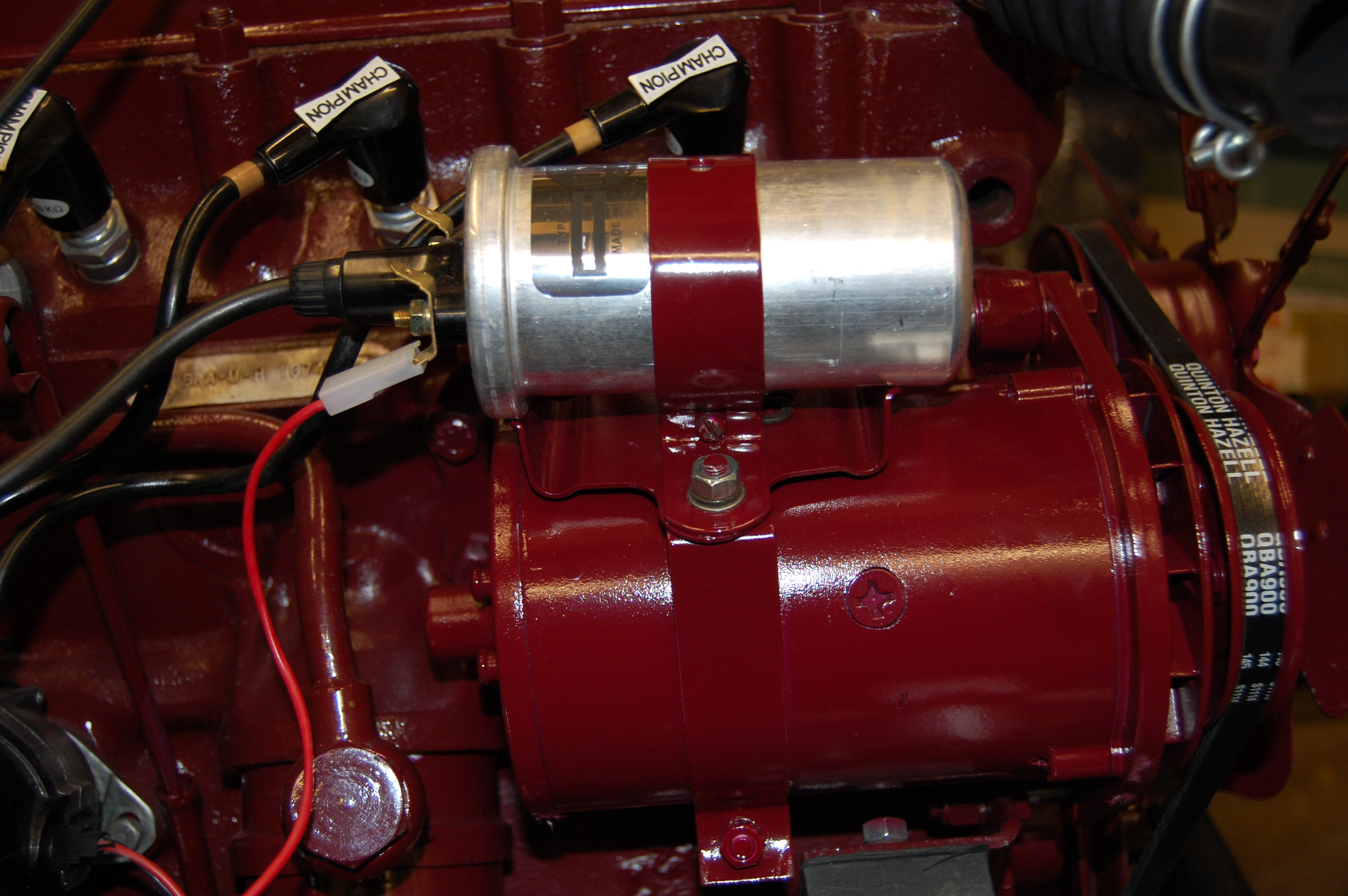
This is the ‘Powerlite Dynamator’ (alternator) , which they say produces 80% more power and weighs 40% less than the original Lucas unit. It was considerably cheaper than the ‘Dynalite’ alternative at £125 purchased through Accuspark, the same unit being sold for in excess of £300 elsewhere. So shop around. The unit is very well made and a straight fit onto the existing mounting brackets, also taking the coil mounting collar and utilising the original fan and pulley. MGA 1500 alternator.
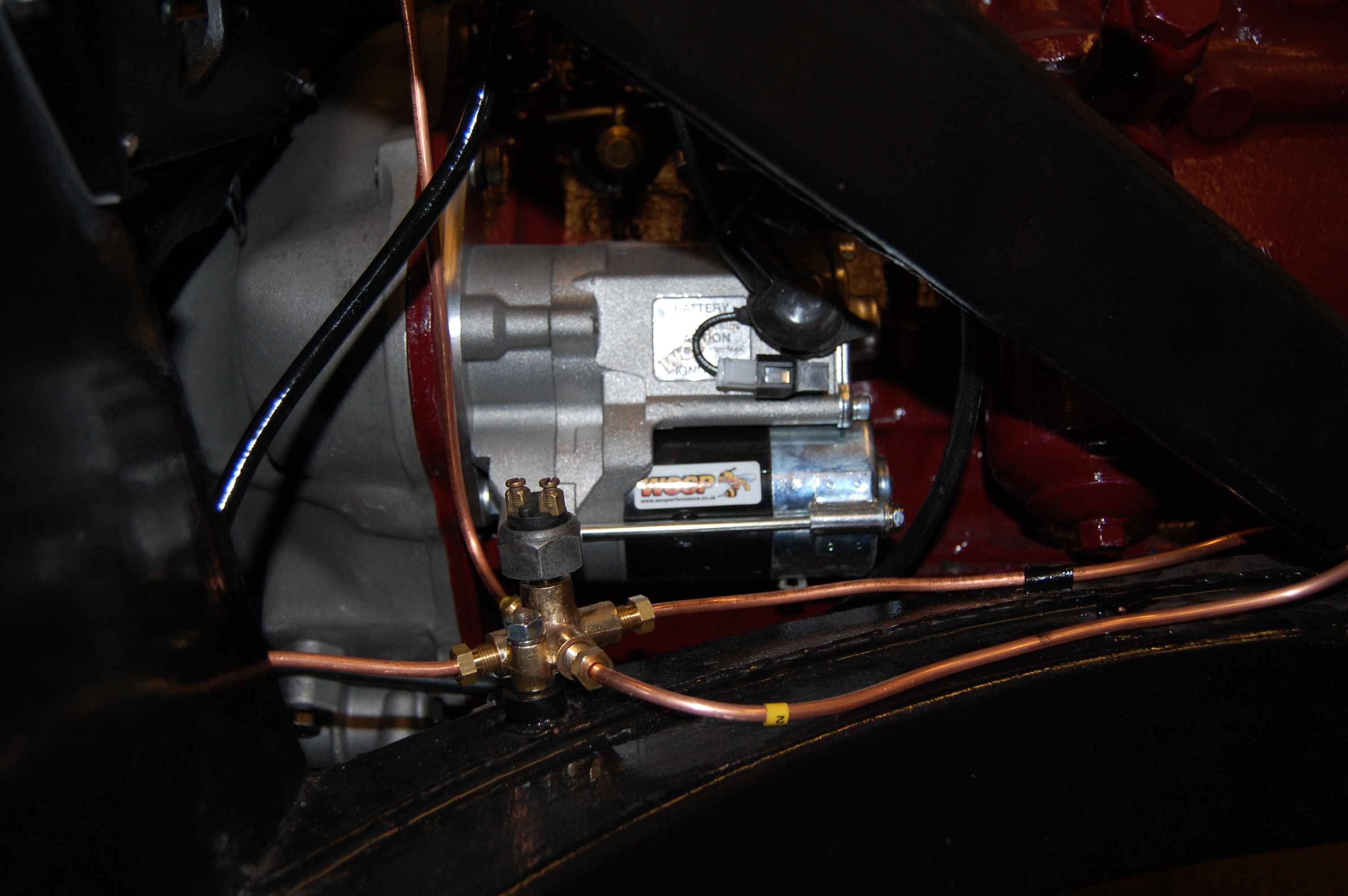
Hi-torque starter
Electronic Ignition
I fitted an Accuspark ignition module, which is a simple fit, relatively inexpensive and retains the original distributor body and cap. Initially the car ran well with it until after only a few hundred miles, the engine would cut out for no apparent reason, although when the engine was hot. Leaving it to cool down enabled it to be restarted, but clearly there was a problem. I changed the module for a new one and for a while it seemed to have cured the problem. Then the same problem started again. At this point I decided to revert to the original points and condenser set up, as if that goes wrong I know how to fix it. Update 2023…with respect to Accuspark, I found that I had the coil low tension/switch wires incorrectly fitted for a negative earth set up, which could have caused the failure.
I purchased the best quality points and condenser that I could find and added spares to carry in the car toolkit. 4000 miles on and the engine performs beautifully, with no problems. I’ve also found it much easier to time the engine.
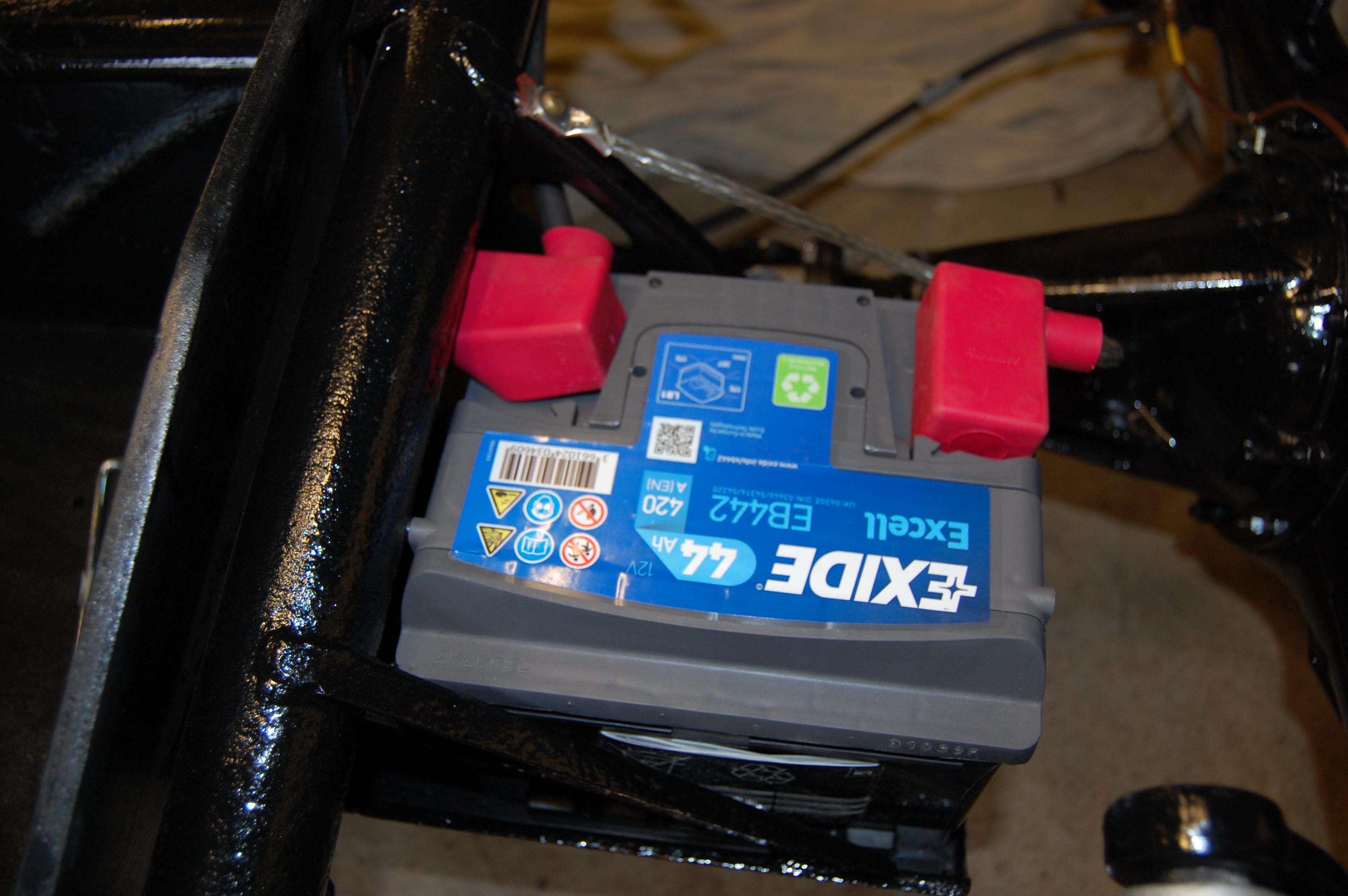
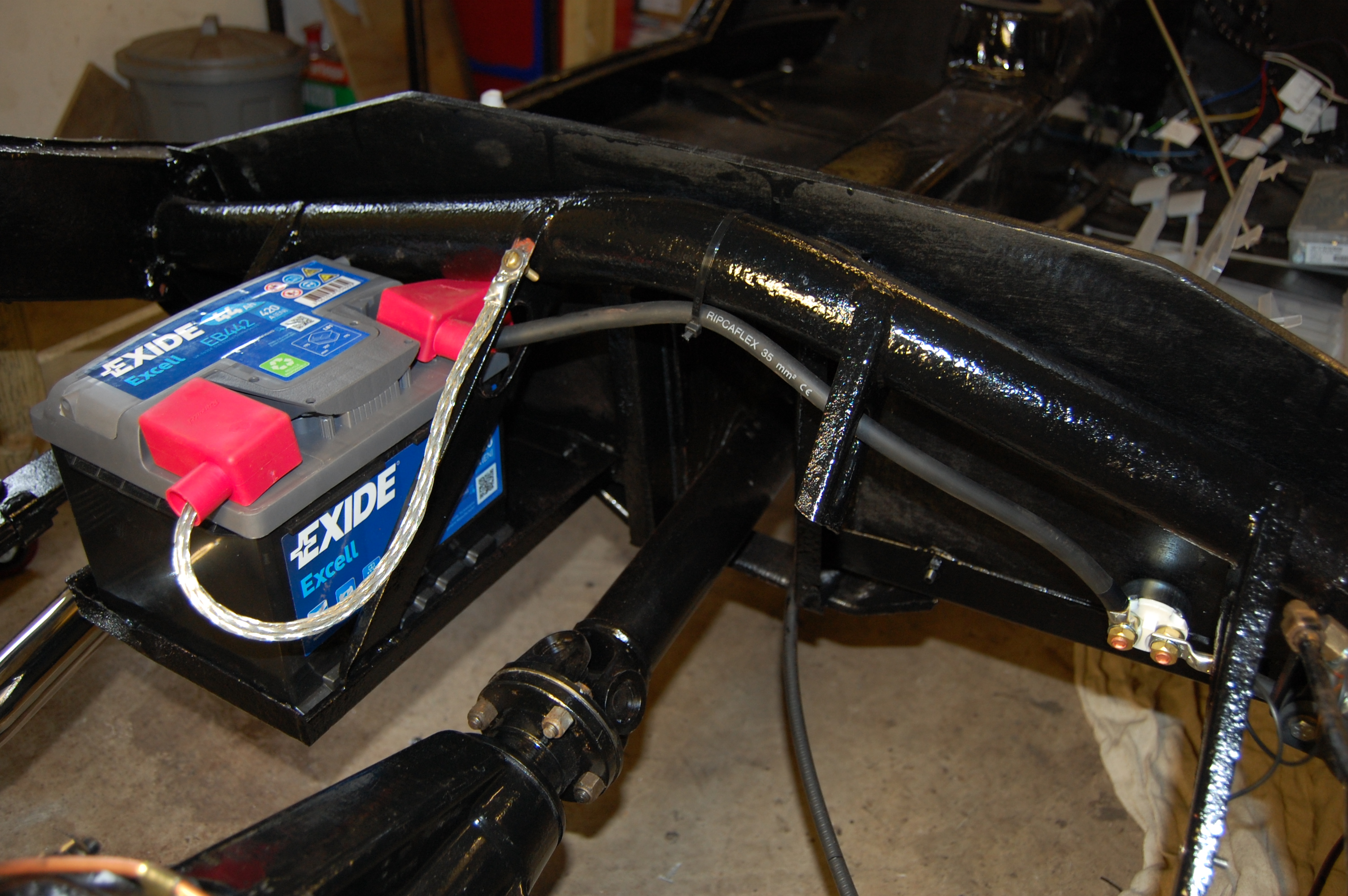
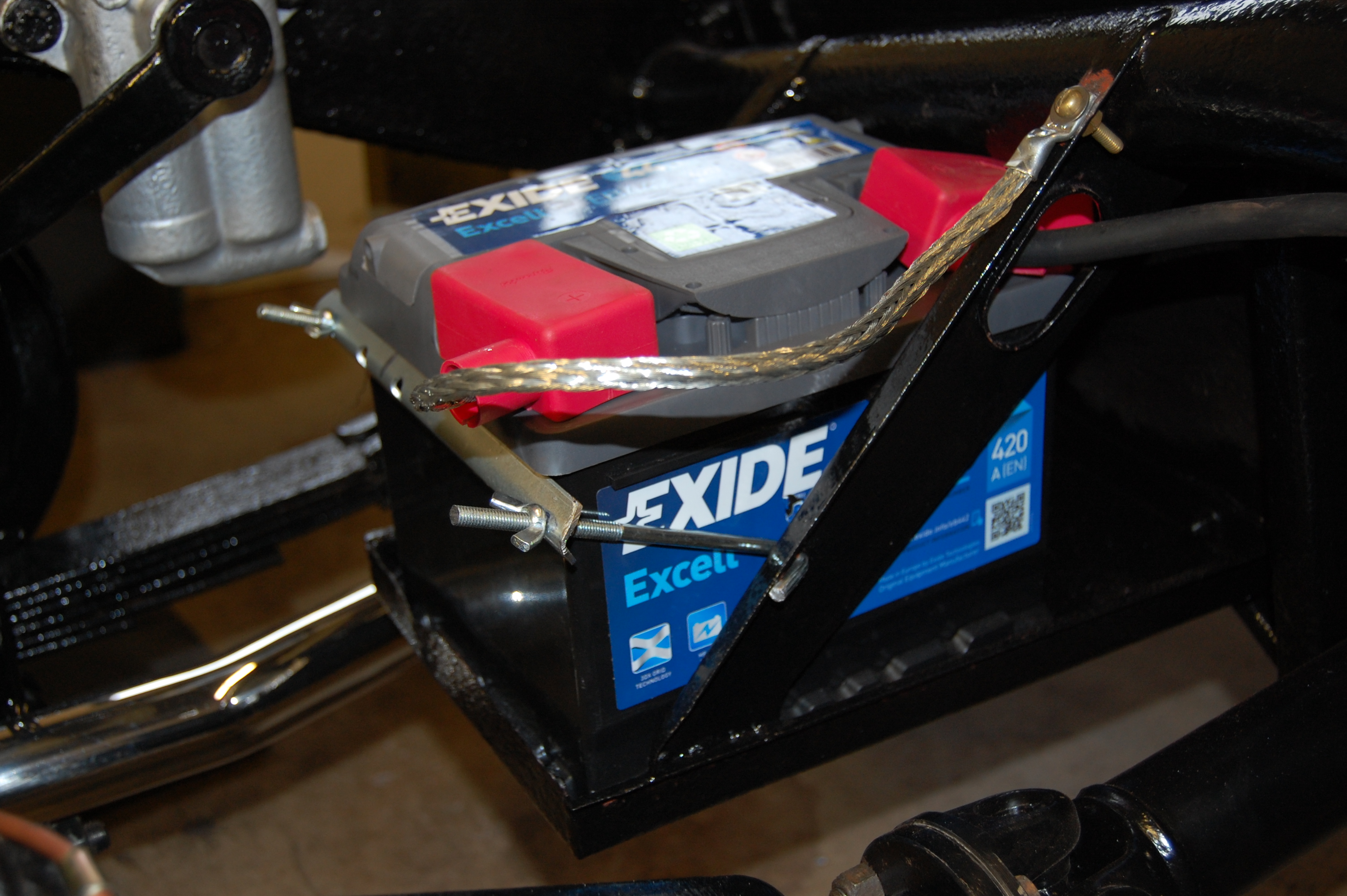
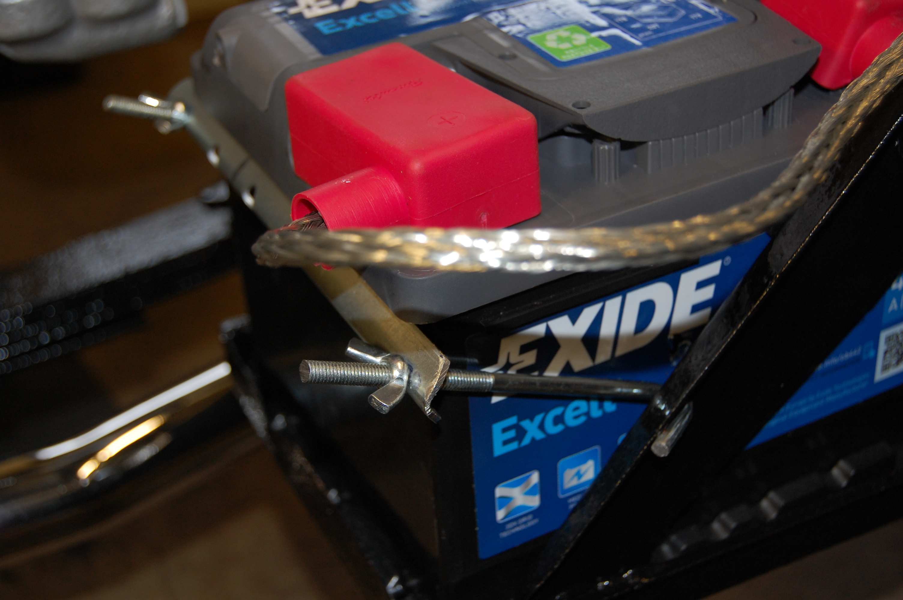
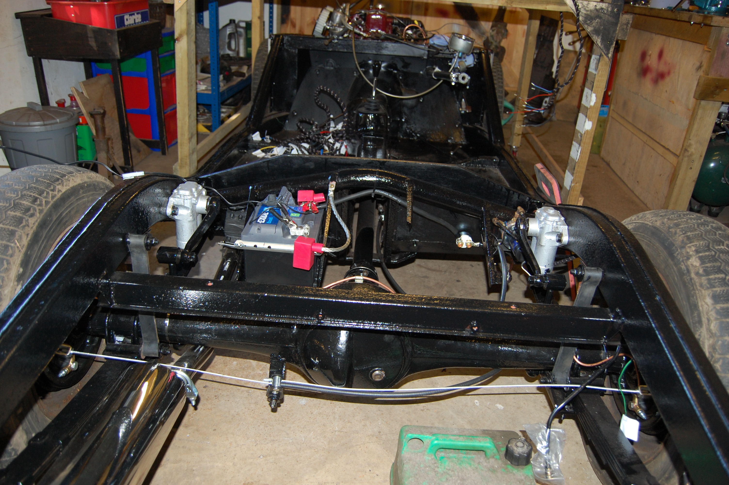
Single battery 12 volt negative earth conversion.
The original MGA spec was of course for 2 x 6 volt positive earth batteries, which carried on through to MGB production. These units are now expensive to replace and less efficient than a single 12 volt unit. My car had been crudely converted to a single battery before my ownership and as I also wanted to fit an alternator, it made sense to do a full conversion.
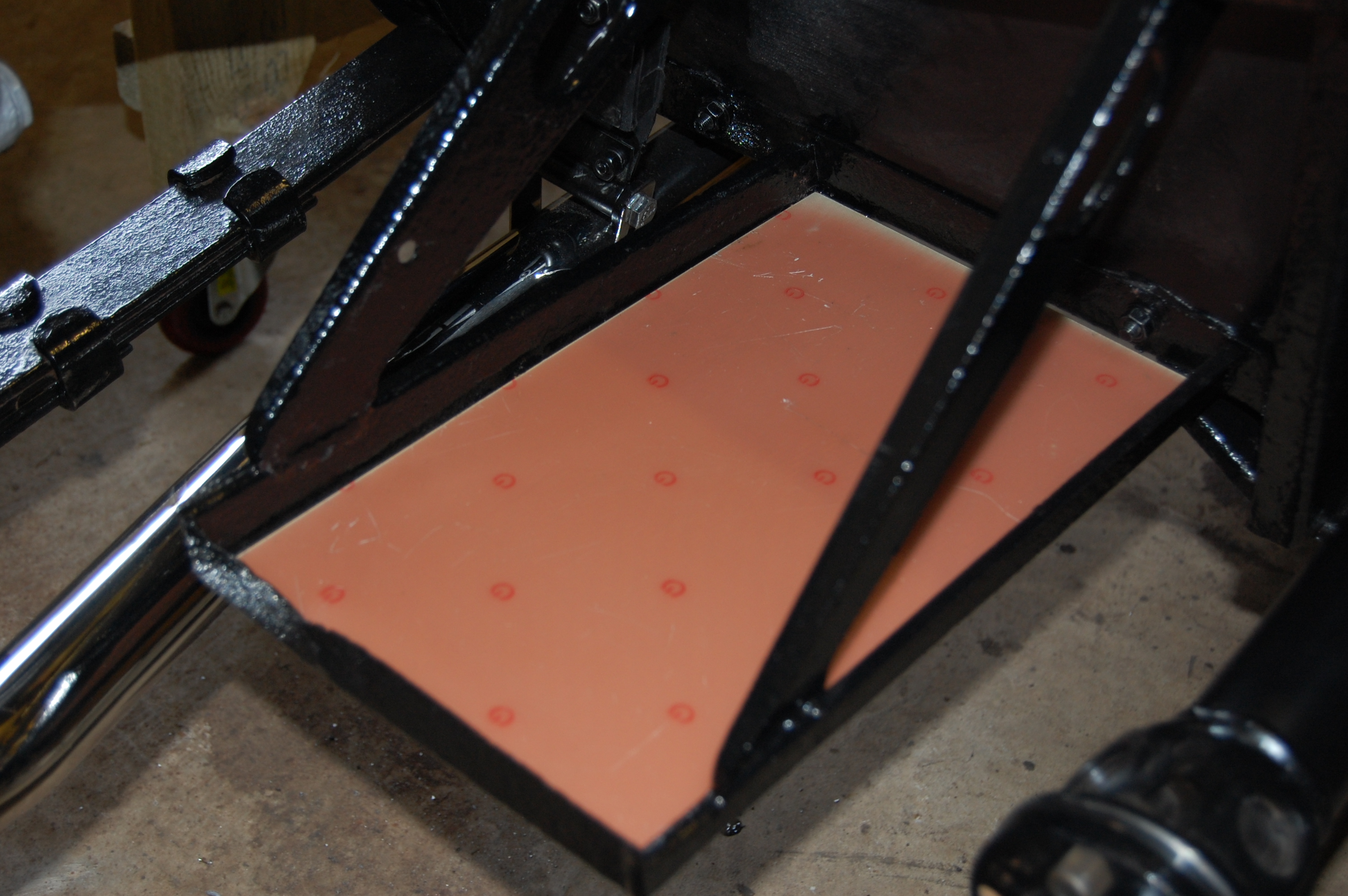
Exhaust under-floor heat shield.
Inertia Reel Seat Belts
My car being a 1959, had no belts fitted or mounting points. As I want to tour in the car with my wife and I want to give grandchildren a ride now and then, I decided full inertia reel seatbelts were a must.
Clearly, this raises problems – where to mount the reels, interference with folded hood/tonneau cover being the main two. I’ve seen a couple of solutions to these where the reel is mounted either on the rear wheel arch within the boot or to the side panel. Both come with problems – intrusion into the useable boot space, unsightly brackets, but mainly that the alignment of the shoulder strap is compromised, emerging throught the cockpit bulkhead in the wrong position. To overcome this last point a secondary guide is needed to position the belt correctly, which further adds to the points mentioned.
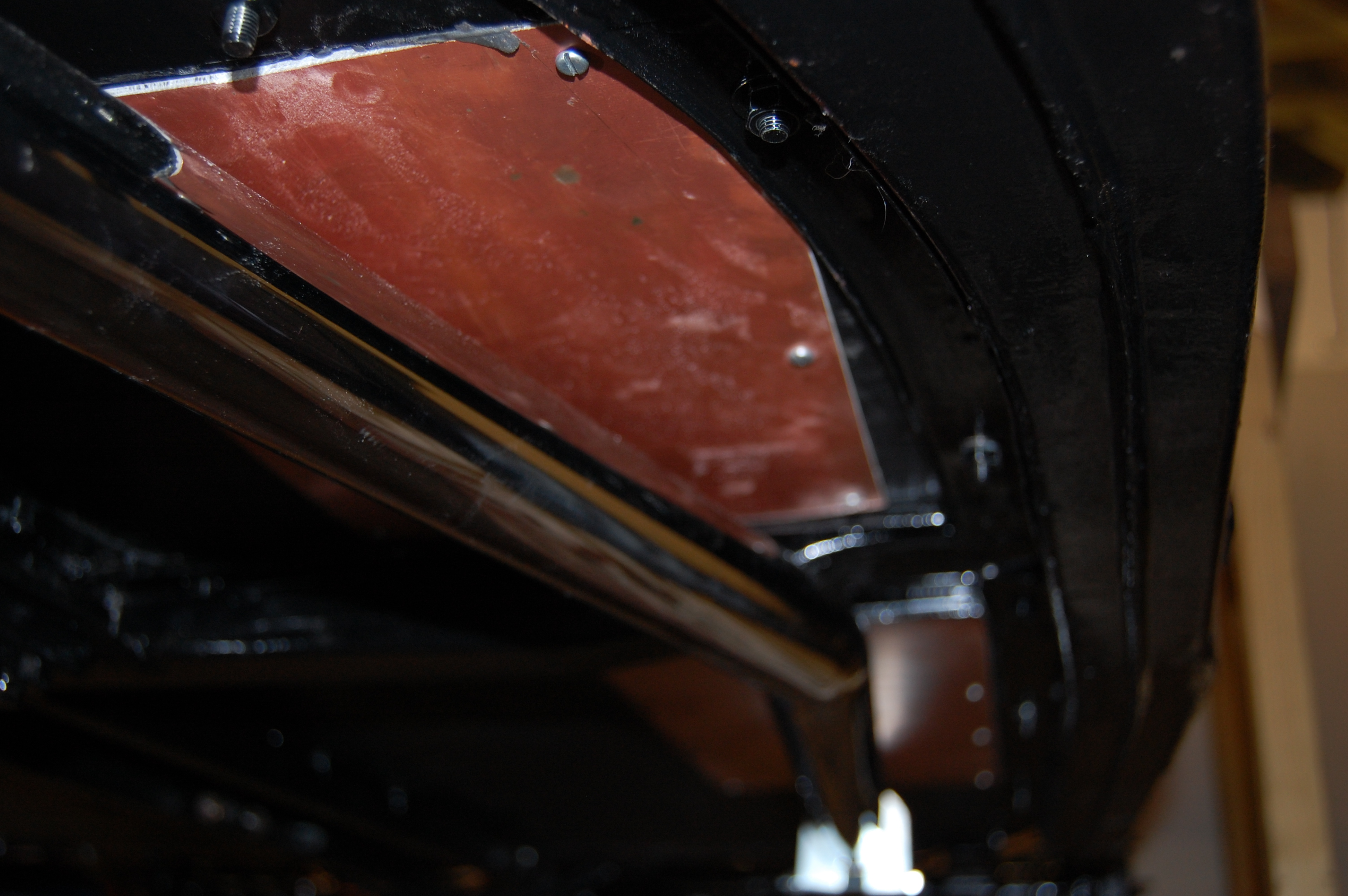
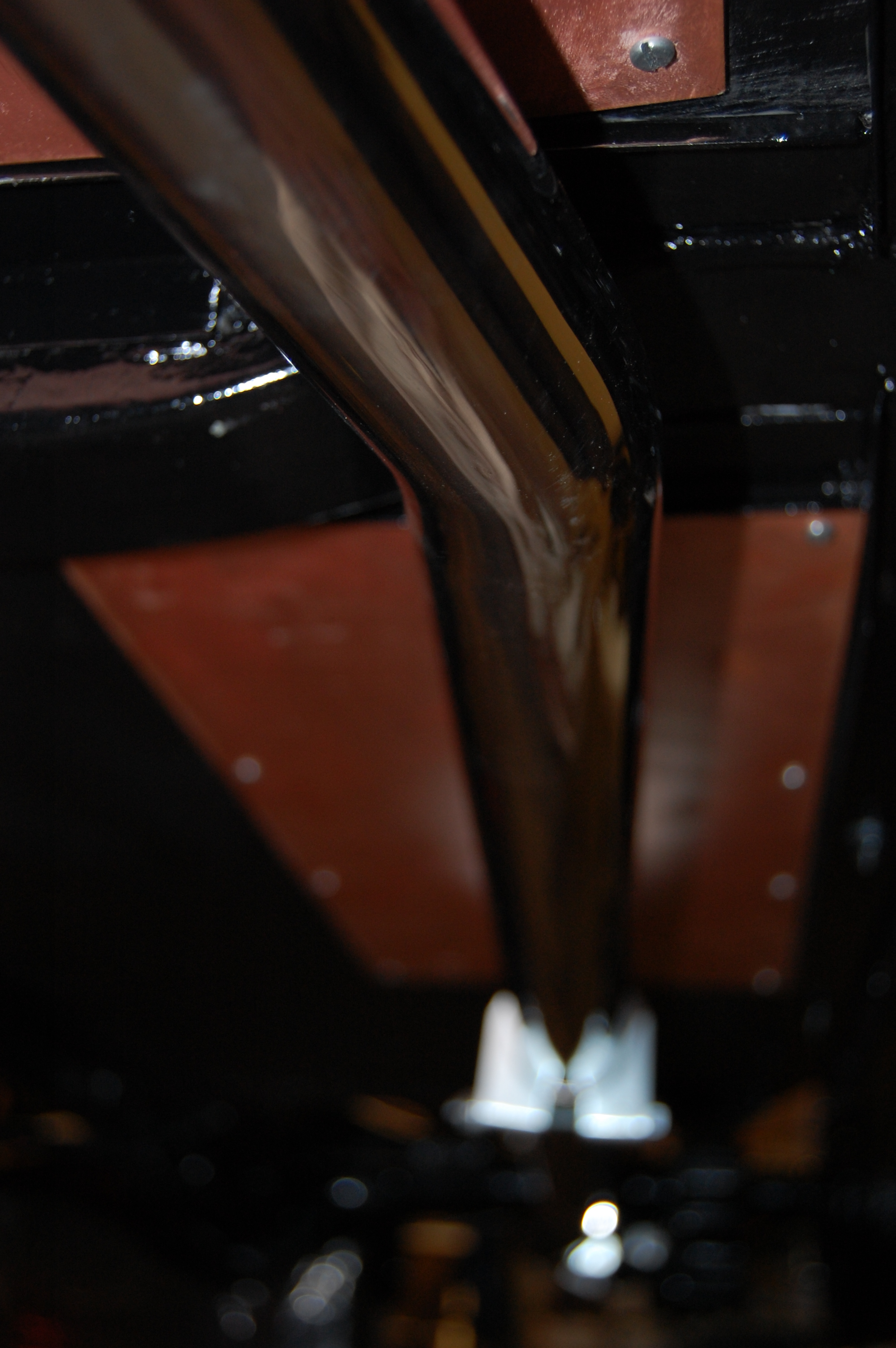
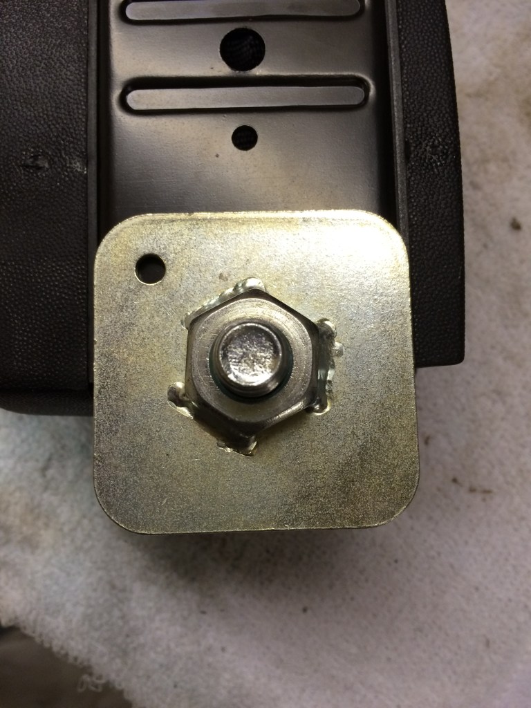
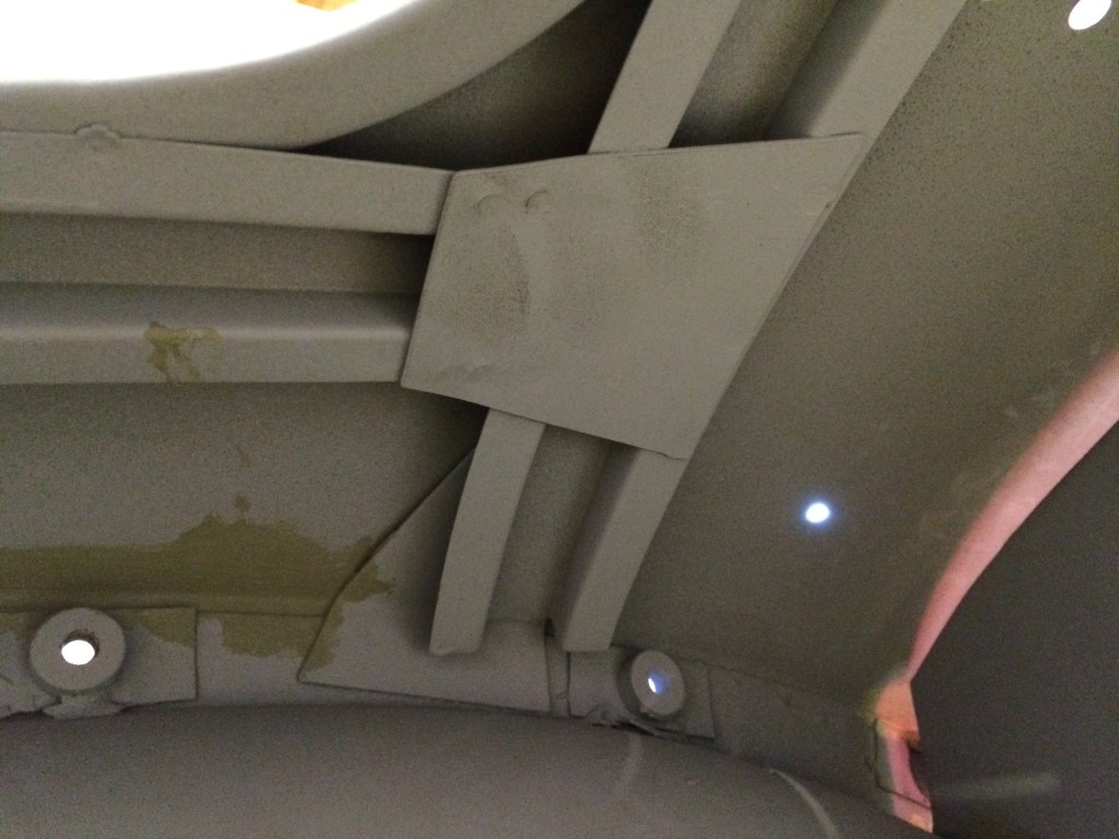
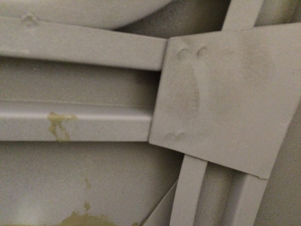
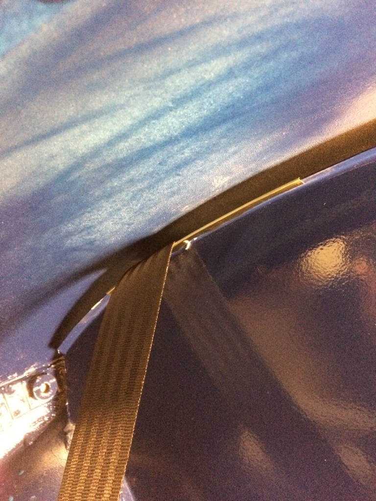
I have come up with a solution, which is relatively simple (if very fiddly) and overcomes the location of the reel problem. Hopefully the photos will give a better idea of how this was achieved, but basically, I utilised the strengthening channel sections, located under the tonneau shelf. These are perfectly positioned to allow the shoulder belt to pass through the bulkhead in the correct alignment and once fitted the reels are solidly and securely mounted.
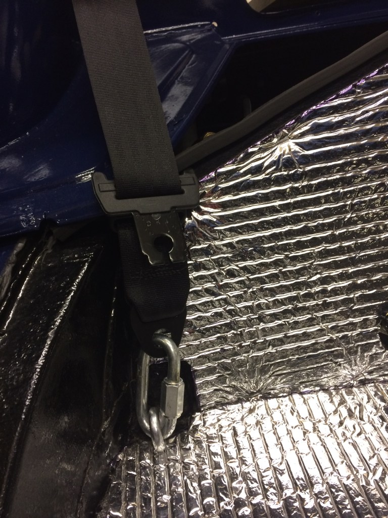
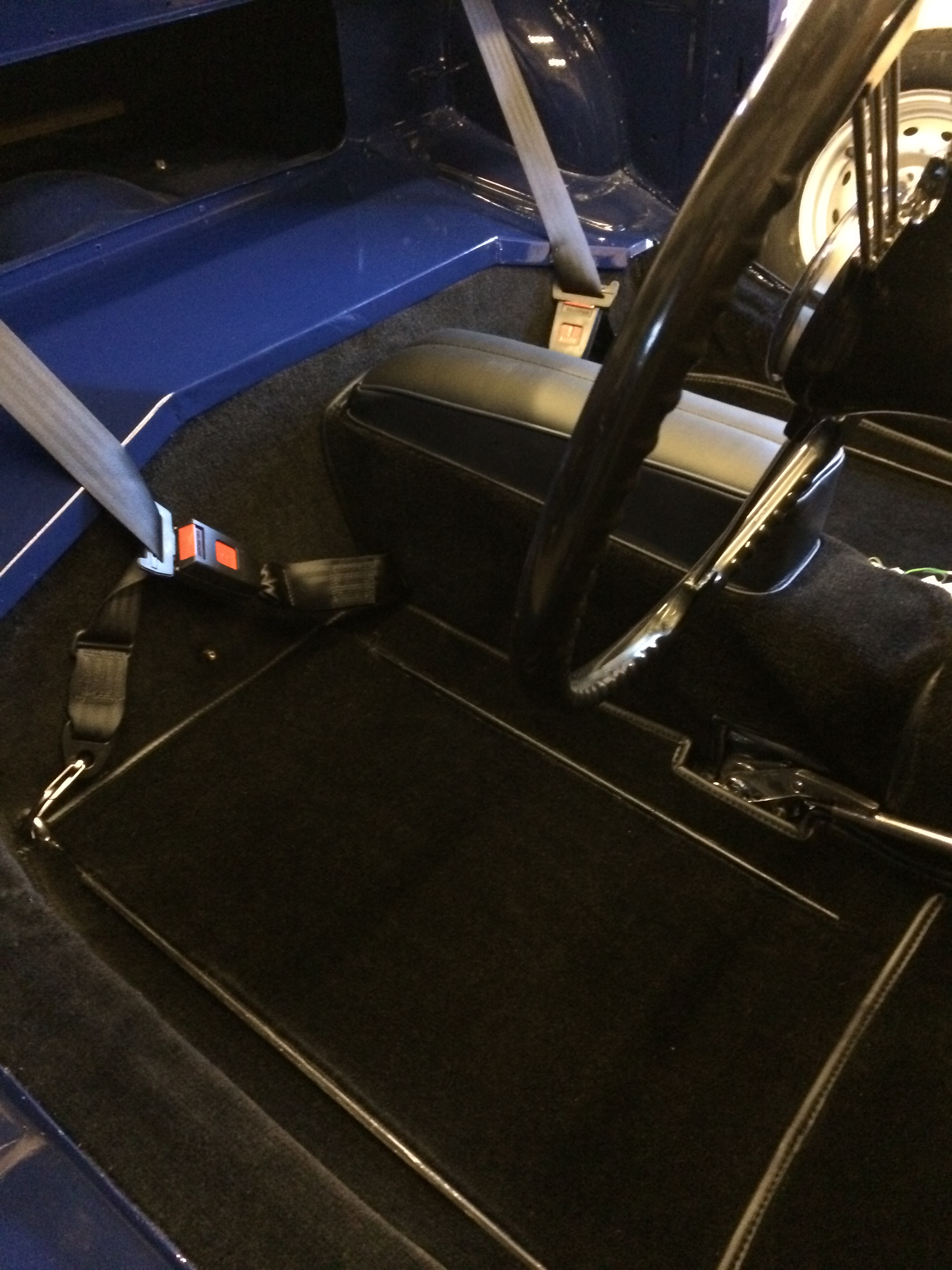
As with other methods I’ve seen, the means of overcoming the need to be able to raise and lower the roof is to fit a removable link in the outboard belt anchor point. In my case, I’ve used a sturdy removable link. I’ve since updated this with a mountaineering carabiner link, which is quicker and easier to unfasten when raising or lowering the roof.
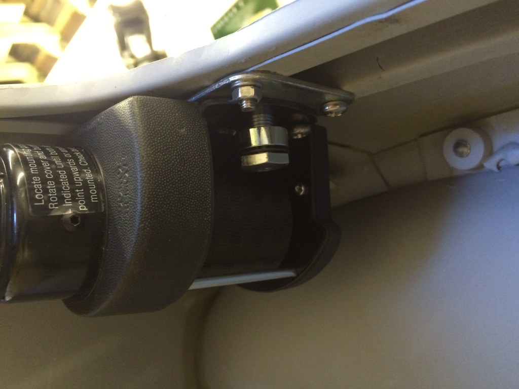
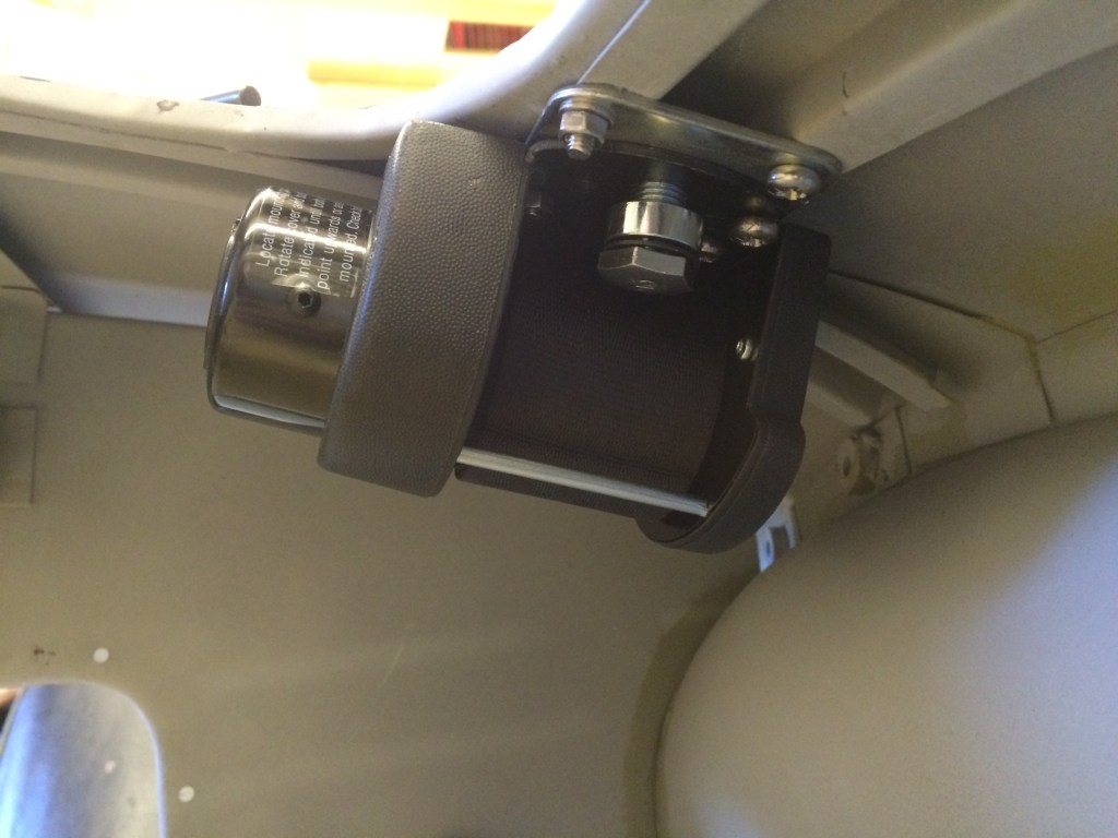
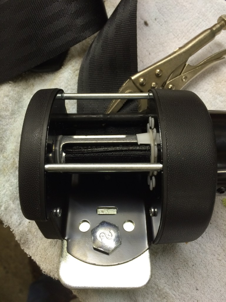
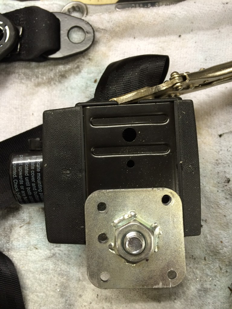
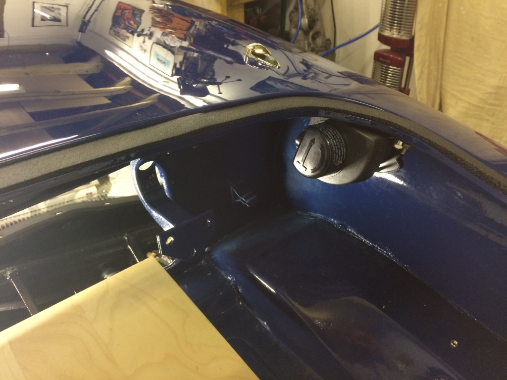
The inertia reel needs to be of the type with an adjustable angle facility, to allow for an inverted location. I used Securon SEC264 belts.
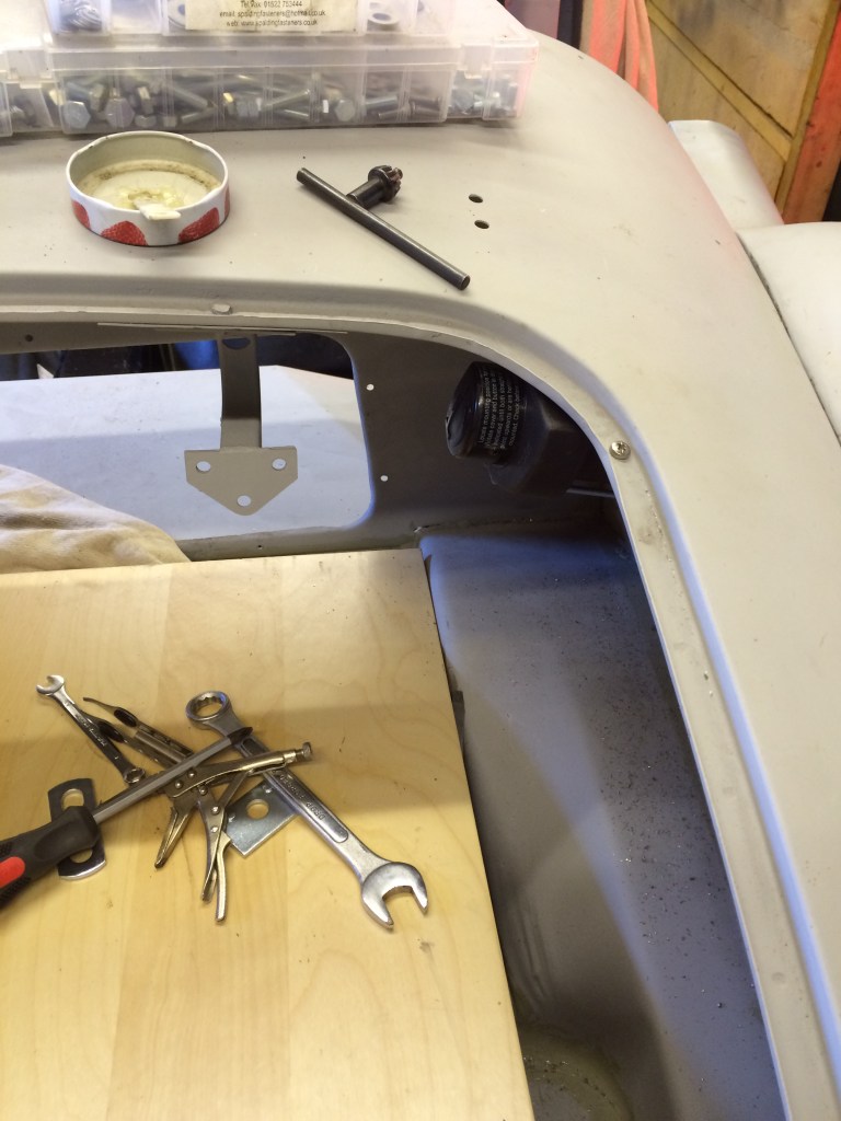
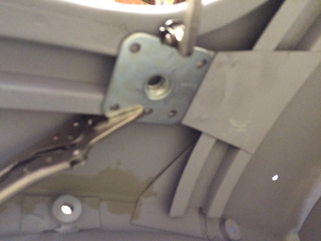
The fitting plate with the captive 17mm bolt could be welded into place or, as I’ve done drilled and fitted with marine grade stainless machine screws. On each reel, one screw does need to be fitted via a drilled hole in the bootlid channel, but when finished, it’s covered by the bootlid sealing strip.
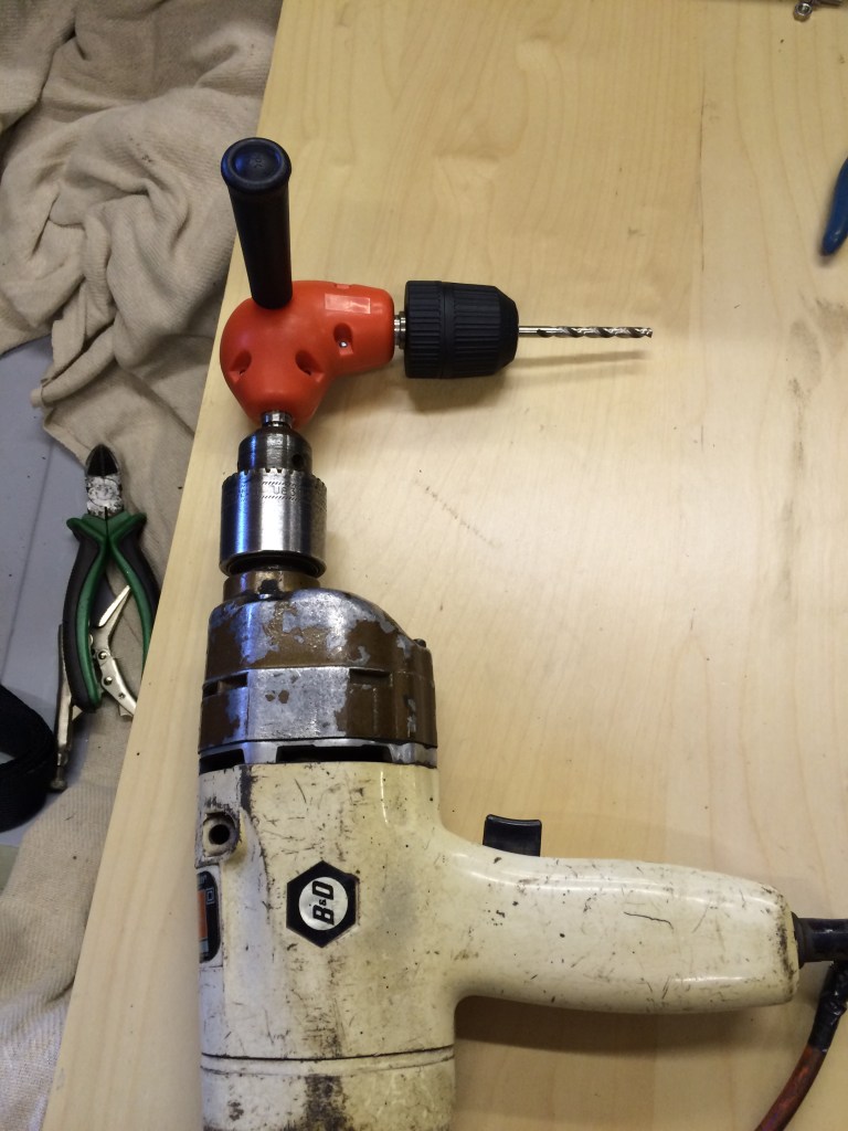
Fitting the bolts is extremely fiddly but not impossible and helped if you have small slender fingers (I don’t!). Also the use of a right-angled drill adaptor is essential, to accomodate working in a confined space. Welding the plate into place is a far more sensible solution, but despite doing all the welding during my restoration, I still lack the confidence to attack, upside down, an area so close to the body.
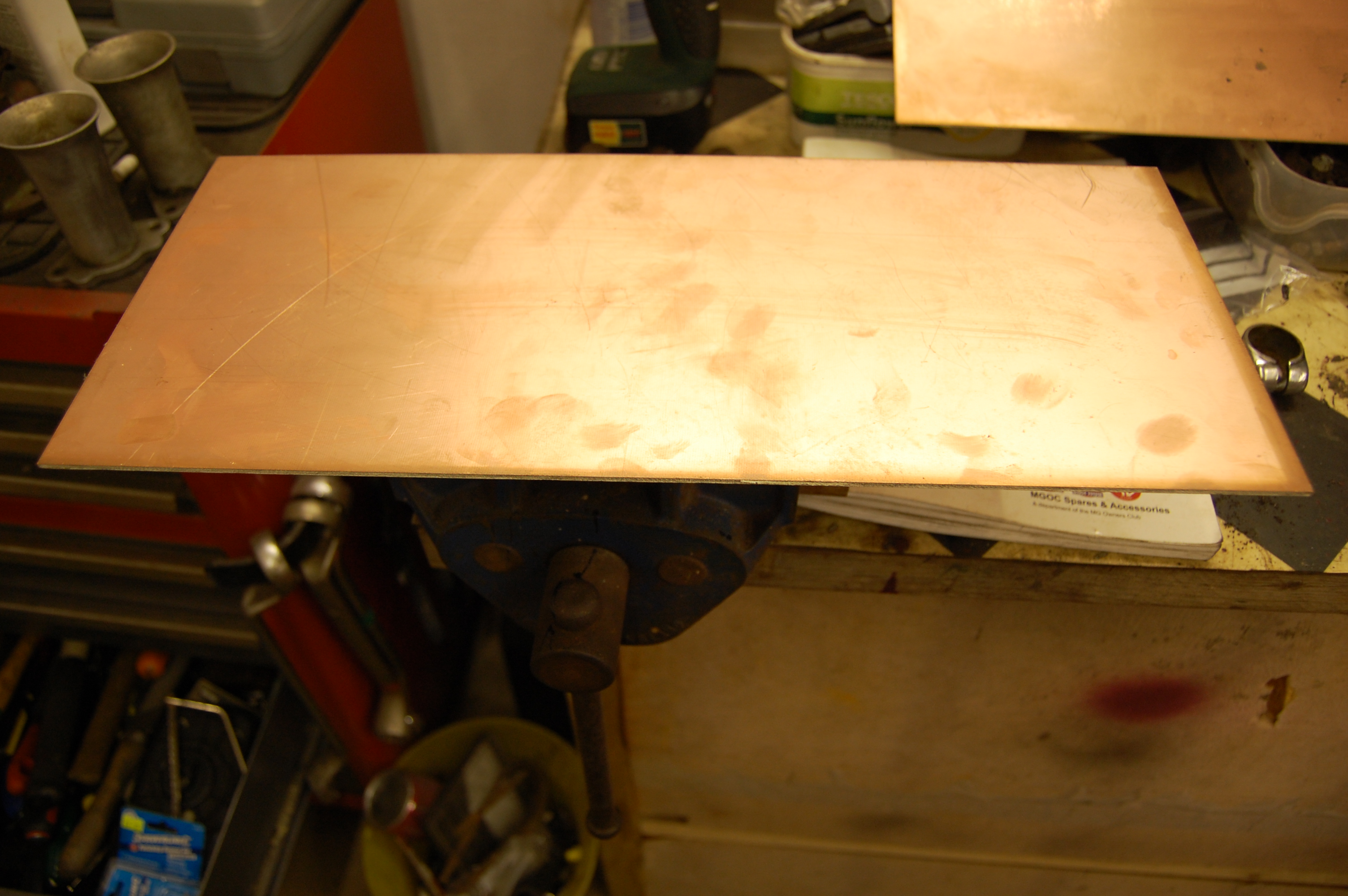
Where the belt emerges over the bulkhead wall, I’ve covered the area with a strip of thin brass shimming strip, which should be smooth enough for the belt to slide easily and not be chaifed. (More photos to follow when complete).
The belts are working well in practice.
USB Charging Port
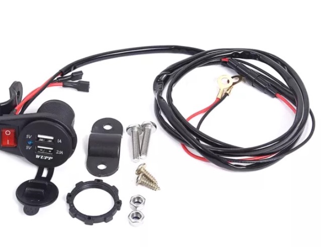
Whilst I don’t want to add too many modern accessories, like it or not, we can’t do without the ability to charge our various devices whilst on the move, so I looked around for a discreet unit.
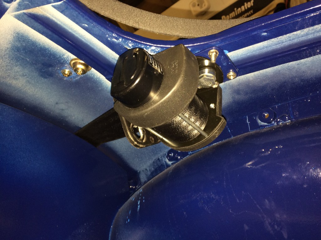
I found one designed for a motorcycle that is waterproof, small and easily fitted out of the way without the need for drilling.
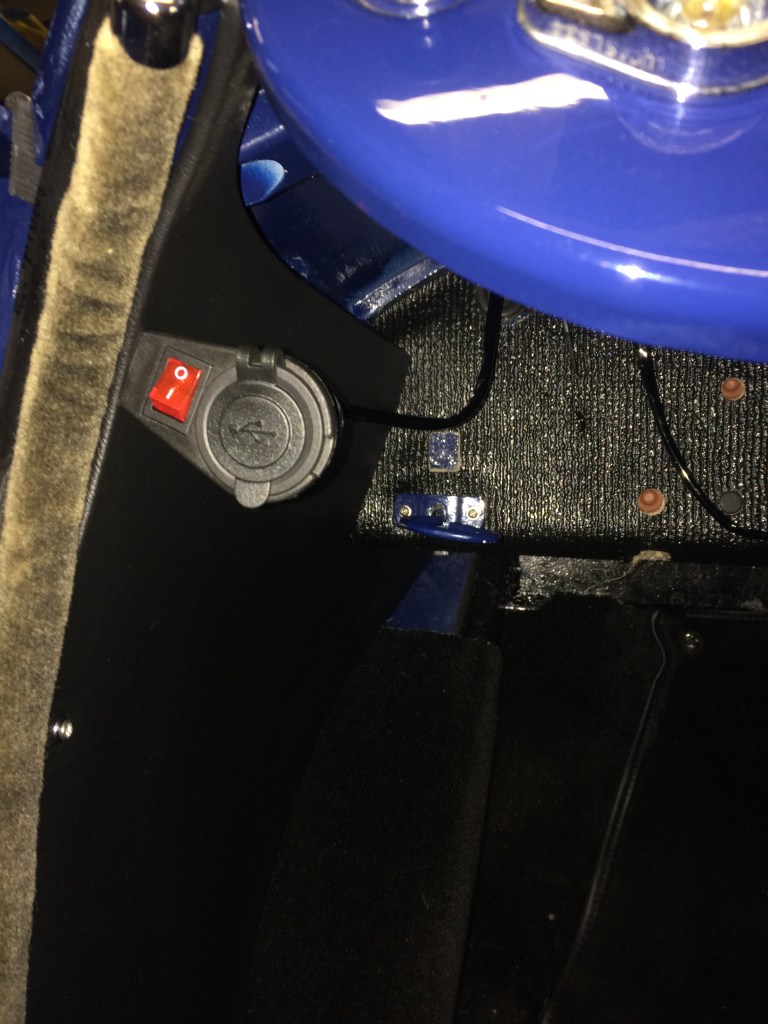
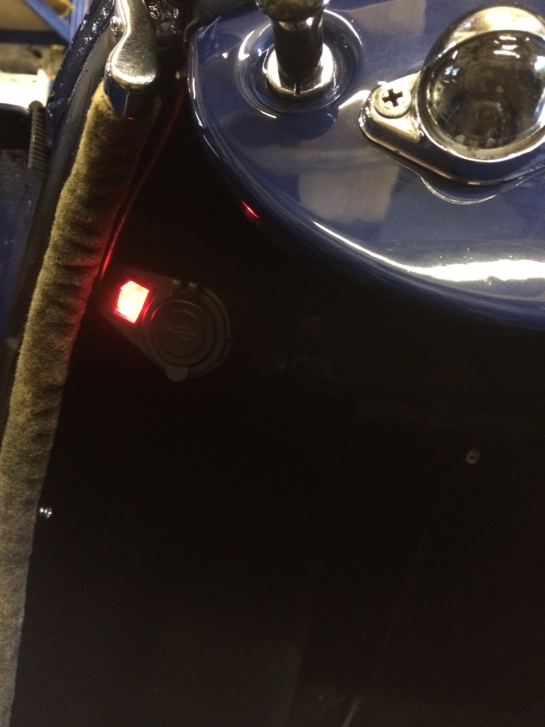
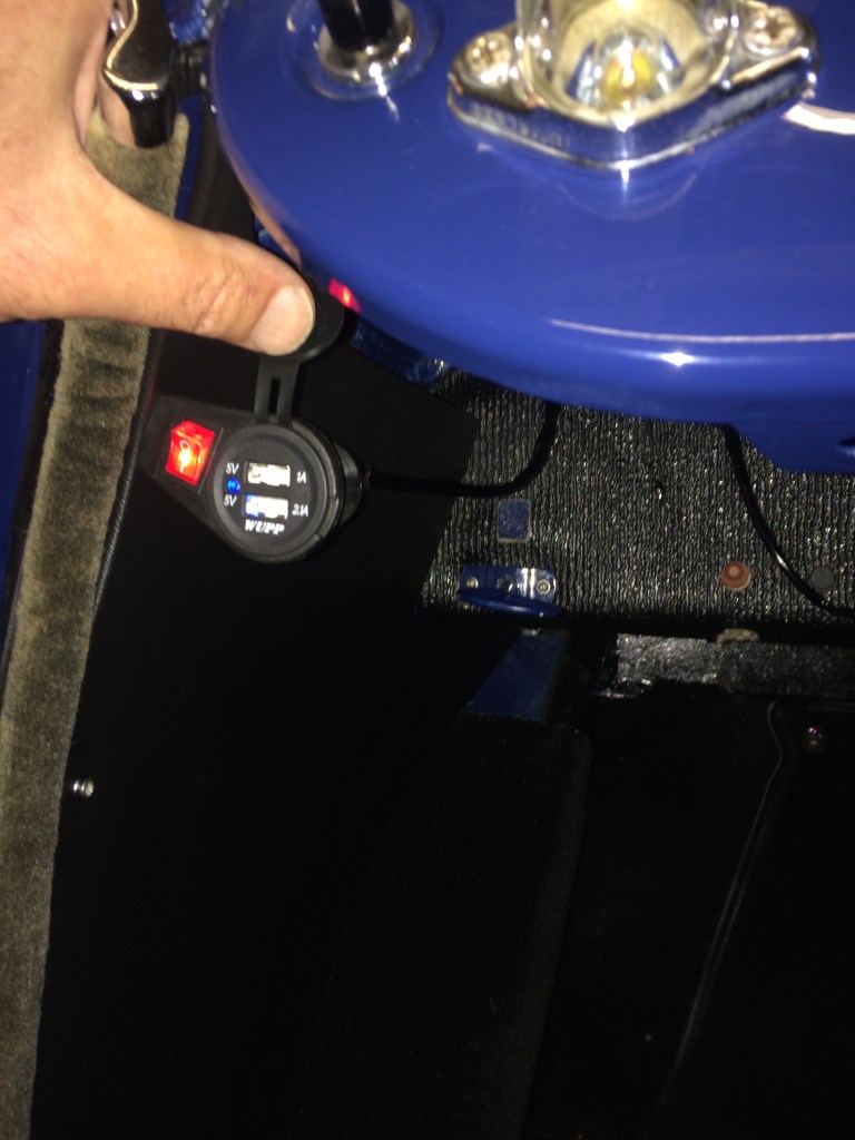
The unit fitted up under the lefthand corner of the dash, using an extended trim screw in an existing drill hole. The pictures make it appear lower than it is… viewed from the seat it is barely visible. The unit has it’s own on/off switch and is live from the bulkhead fuse block. This enables charging with the ignition off.
Sun Visors
LED Third Brake Light
I often take the A out for a late afternoon spin on a fine day and it usually involves driving into a low sun, at some point. With the roof down and no sun visors, I’ve relied on a peaked hat and sunglasses, but it’s not really effective.
I recently saw a pair of tinted visors on a TR3 and gleaned from the owner that they were a Tourist Trophy product, bought through Moss. So I bought one in a Moss discount sale to test on the A. It’s ideal, fitting onto the top edge of the windscreen frame by slim clamps, each with a small Allen grub screw, identical to T T’s side wind deflectors.
I also tried it with the roof erected and provided the underside of the roof header has a soft sealing strip as mine does, it seals over the visor clamps, without leakage.
They’re not cheap at £36.00 inc postage from Moss, but worth every penny in practice, offering a really excellent sun filter.
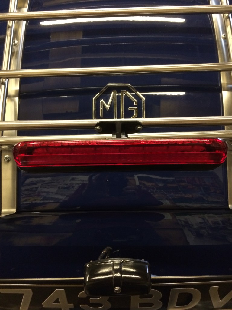
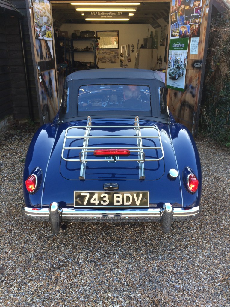
Having been driving the car for 1300 miles, my only reservation had been the feeling of vulnerability from behind due to the low, small rear brake lights.The speed of modern traffic mixed with the size and height of vehicles really demands a more obvious rear brake light.
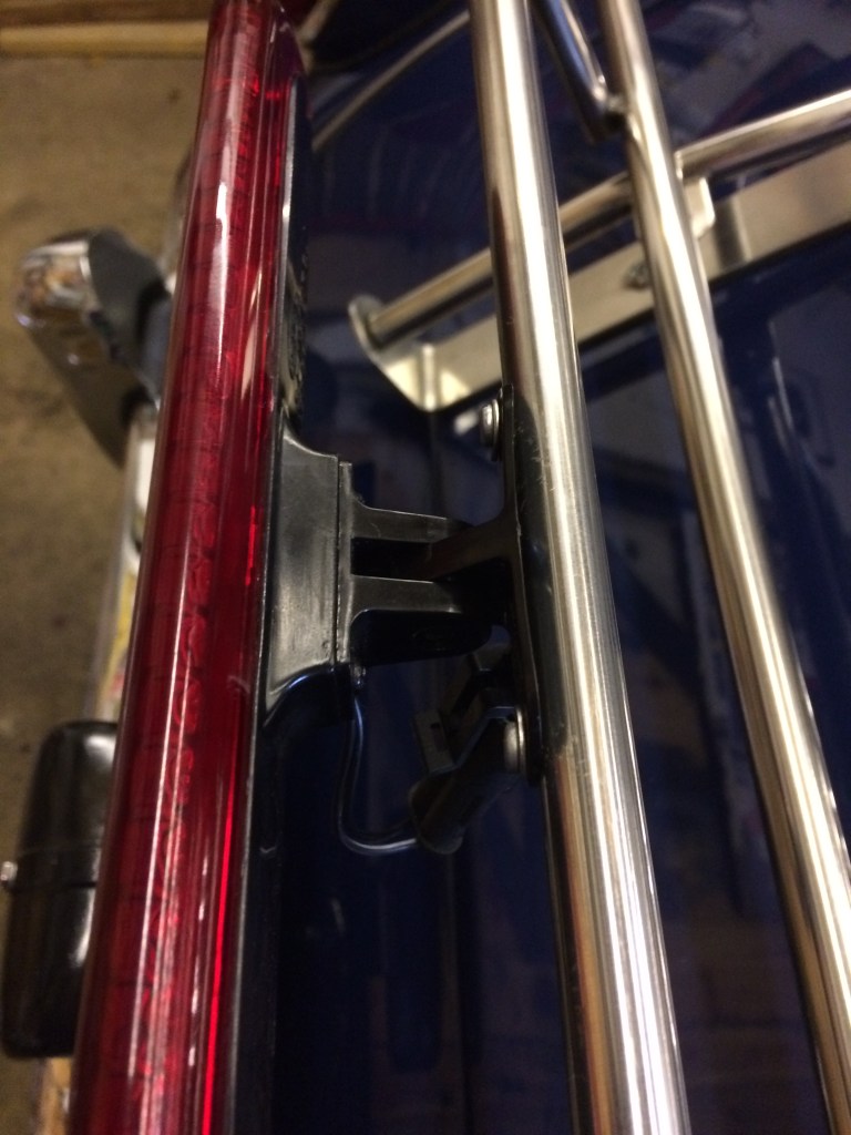
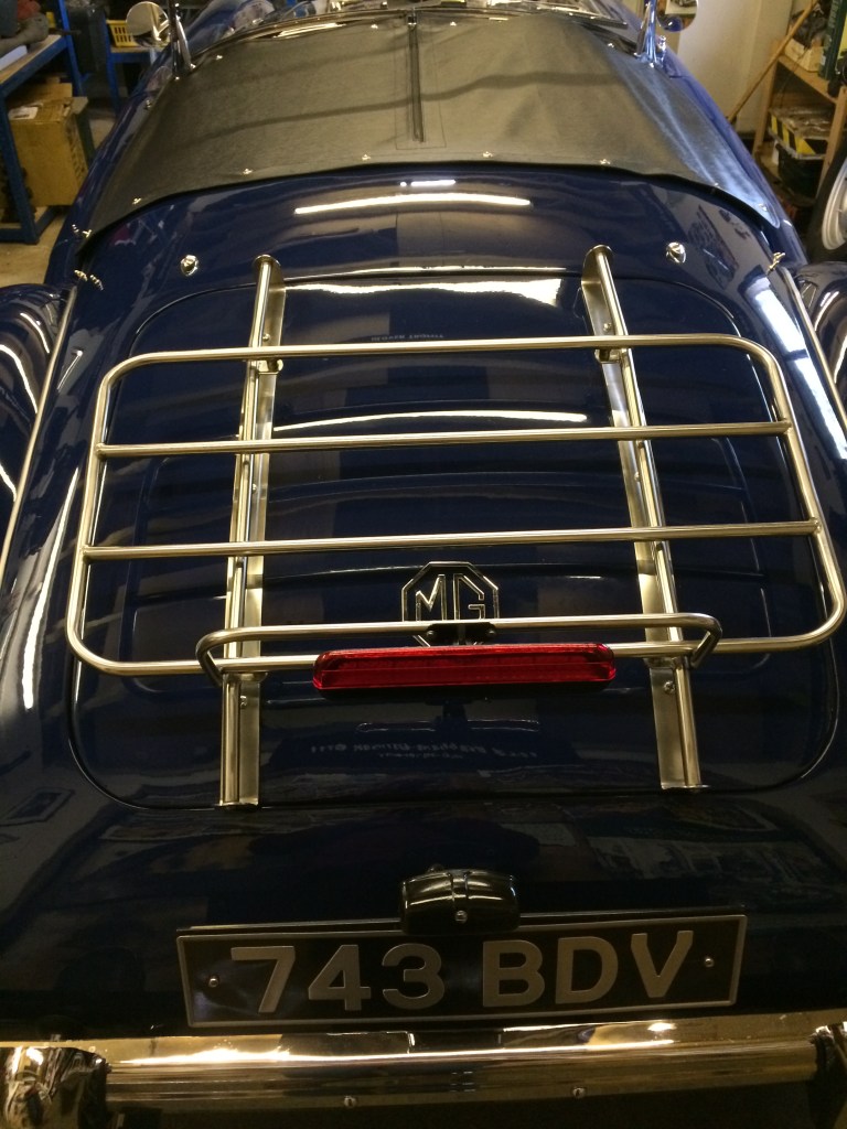
I started by buying a new LED single strip light unit which came with a simple bracket and wiring. I decided that the best place for the unit is for it to be mounted on the high rear tube of my luggage rack, as in that position it an be seen even when the rack is laden.
Mounting the unit on the rack also gave the opportunity of hiding the wiring in the tubing, with the wire then entering the boot by one of the rack securing bolt holes .
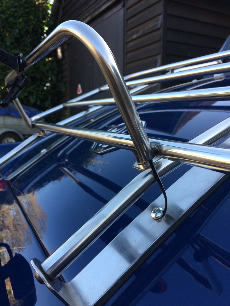
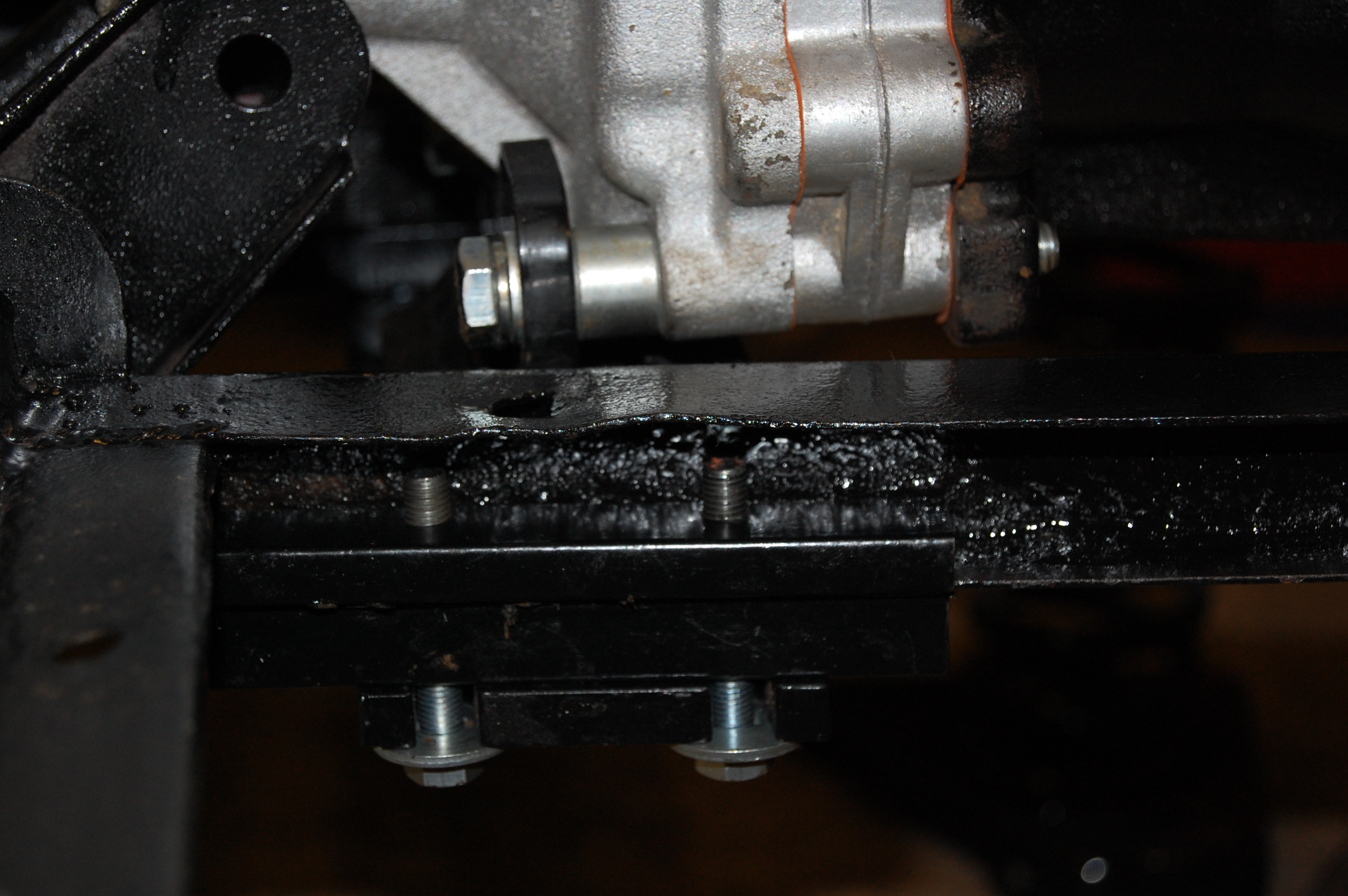
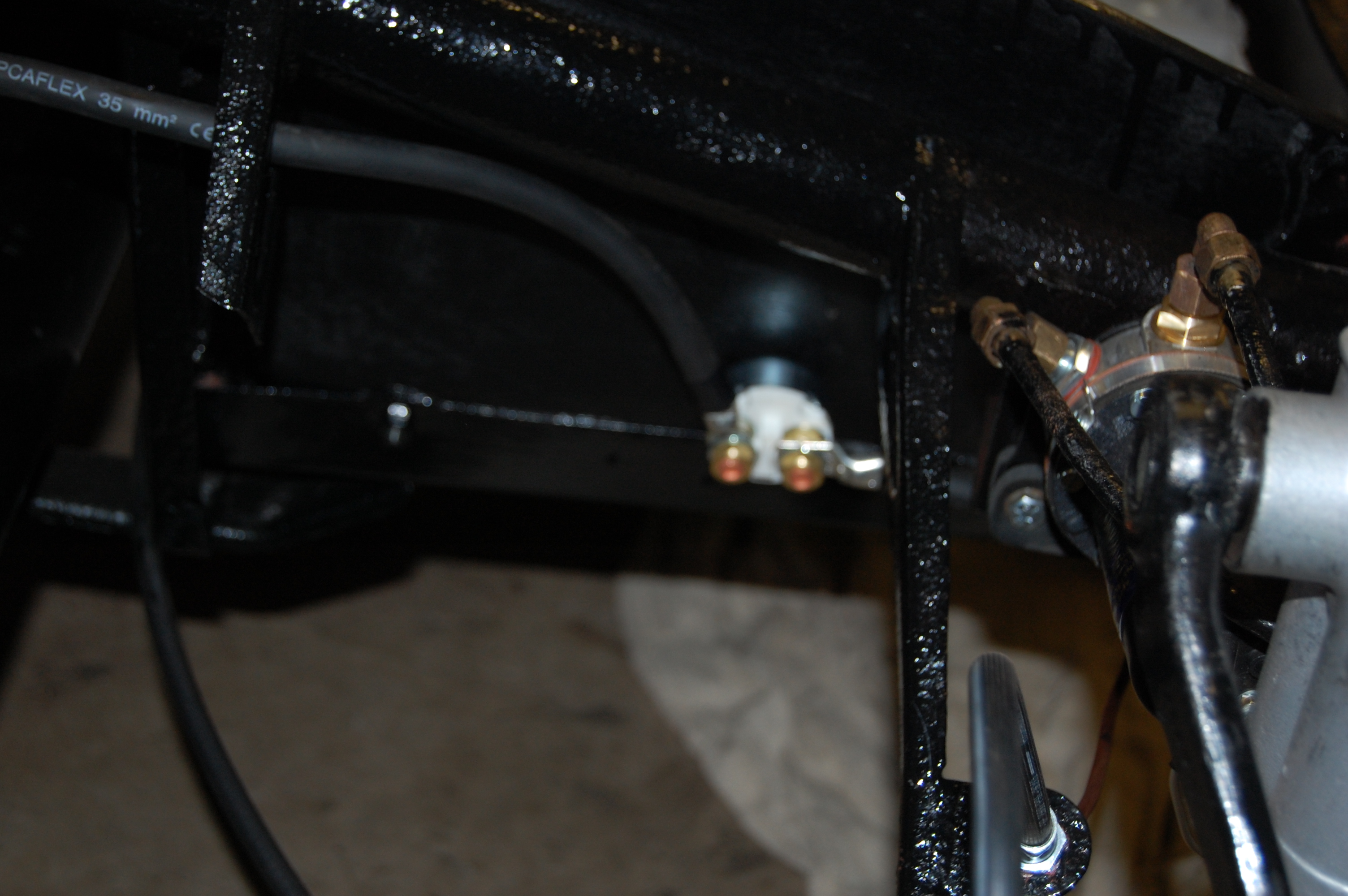
On a 1500 with the combined rear lamp unit, it’s not possible to connect up to the brake light circuit at the lamp, so the option is to run a wire up to the brake pressure switch, mounted on the right hand chassis rail beneath the engine bay, adjacent to the starter motor.
My wire routing took the wiring from the lamp through the rack tubing, down into the boot via the nearest rack mounting bolt, across the roof of the boot to the hinge where it turns right towards the inner wing. Here a small hole was drilled with a rubber grommet, to take the feed wire and earth (ground) through the inner wing where the earth wire picks up a grounding point on the nearest chassis tab that carries the loom and the feed wire follows the loom all the way along the chassis to the pressure switch .
From a visual point, I used a black wire, which I heat shrink wrapped where exposed, so that it’s not too obvious.
The lamp unit worked well, but in practice after a few miles, the vibrations through the rack caused the lamp unit to work it’s way to a downward angle. This was overcome by reducing the length of the hinged mounting post and fitting a more robust fixing bolt.
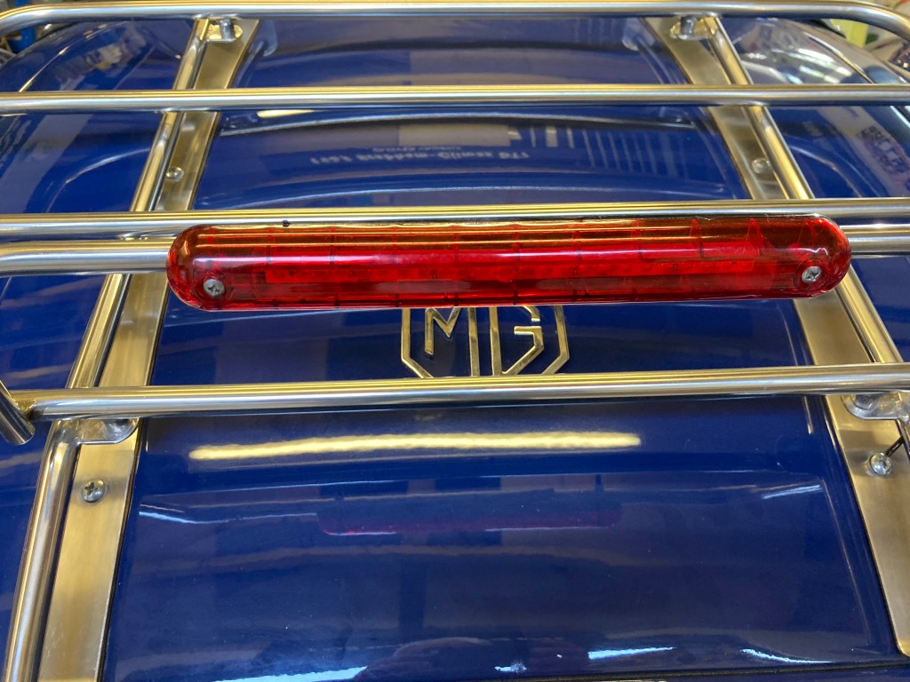
Finally, I realised that the light unit is designed to be fitted flat rather than upright as in the pictures, as the led lights are displayed along the length of the lamp side (sounds confusing!)
This was easily rectified by removing the lamp and refitting in the correct plane.
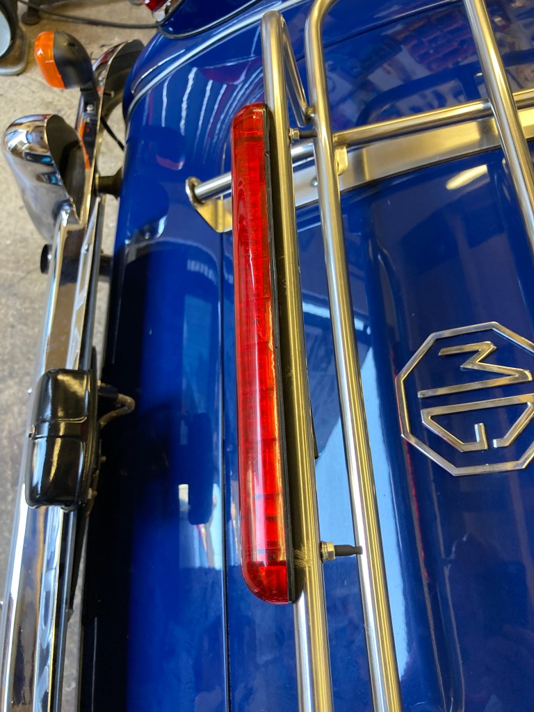
May 2022 Update – I’ve now fitted a replacement LED brake light that is a simpler design and fits more discreetly on the rack tubing. It’s also more solid, as it fits directly onto the tube with two stainless steel bolts.
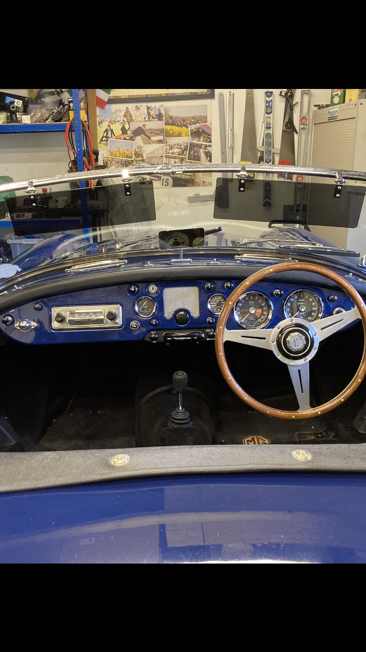
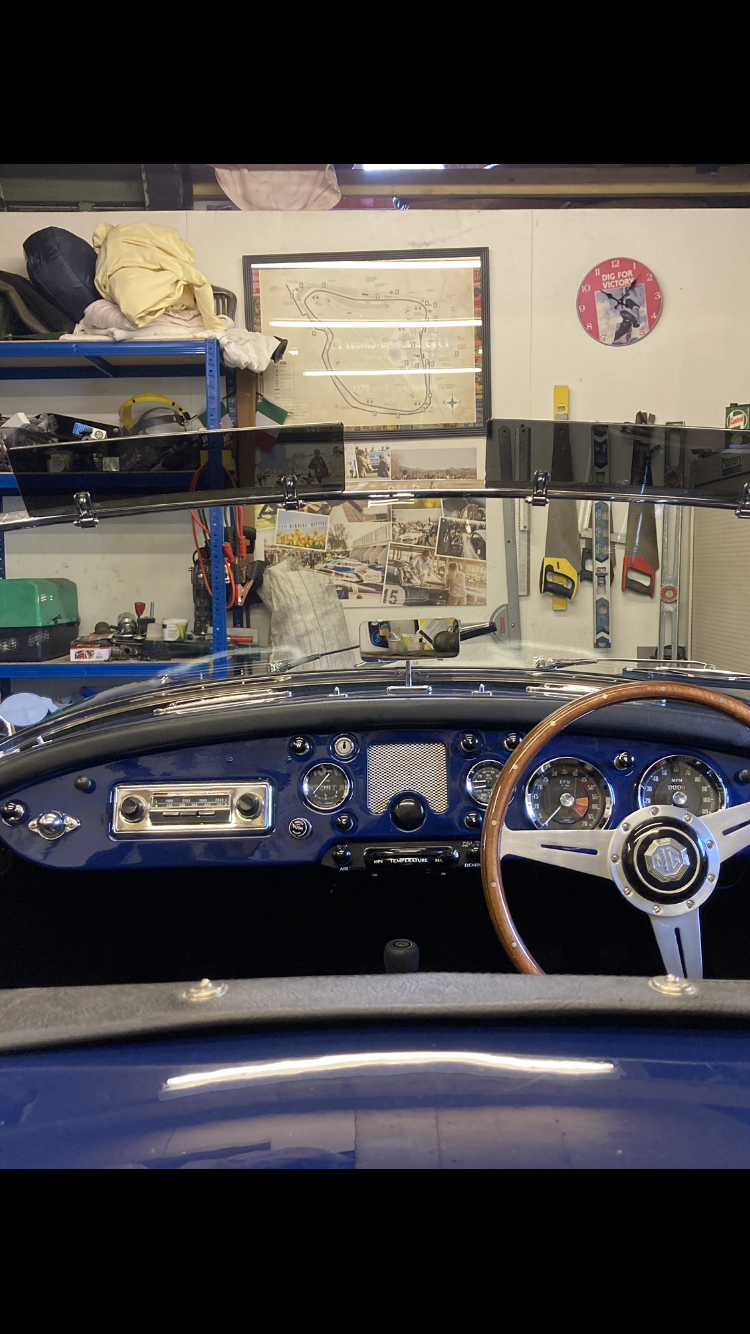
Tourist Trophy Steering Wheel
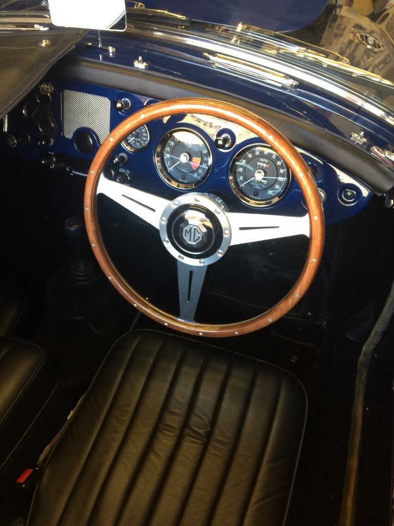
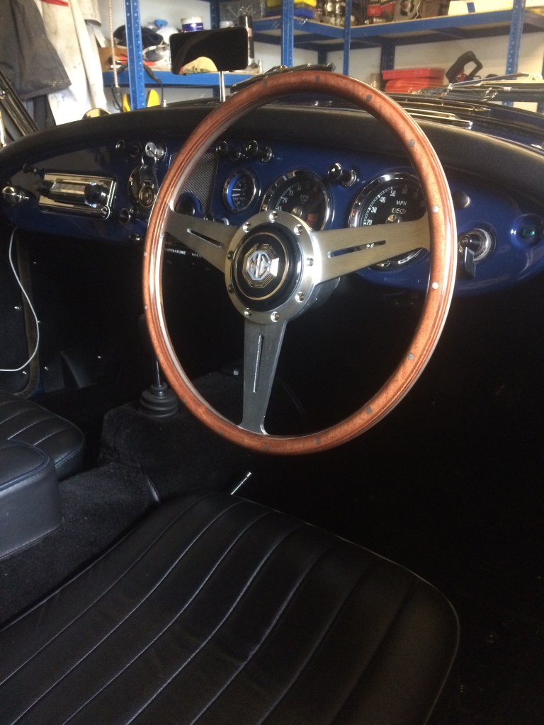
I bought this steering wheel a few years ago, but have resisted fitting it because I love the period look of the original black one. Having some rare time on my hands, I decided to fit it and have a drive……. it was a revelation. Thanks to the smaller diameter, it’s much easier getting in and out of the cockpit and on the road it transforms the driving experience to a new level. The steering input required is so much less, making maneuvers such as roundabouts and junctions a quick flick rather than a major turning of the wheel. It’s also nice not to have the wheel resting on your thighs and by the way, it does look and feel great. I think it stays!
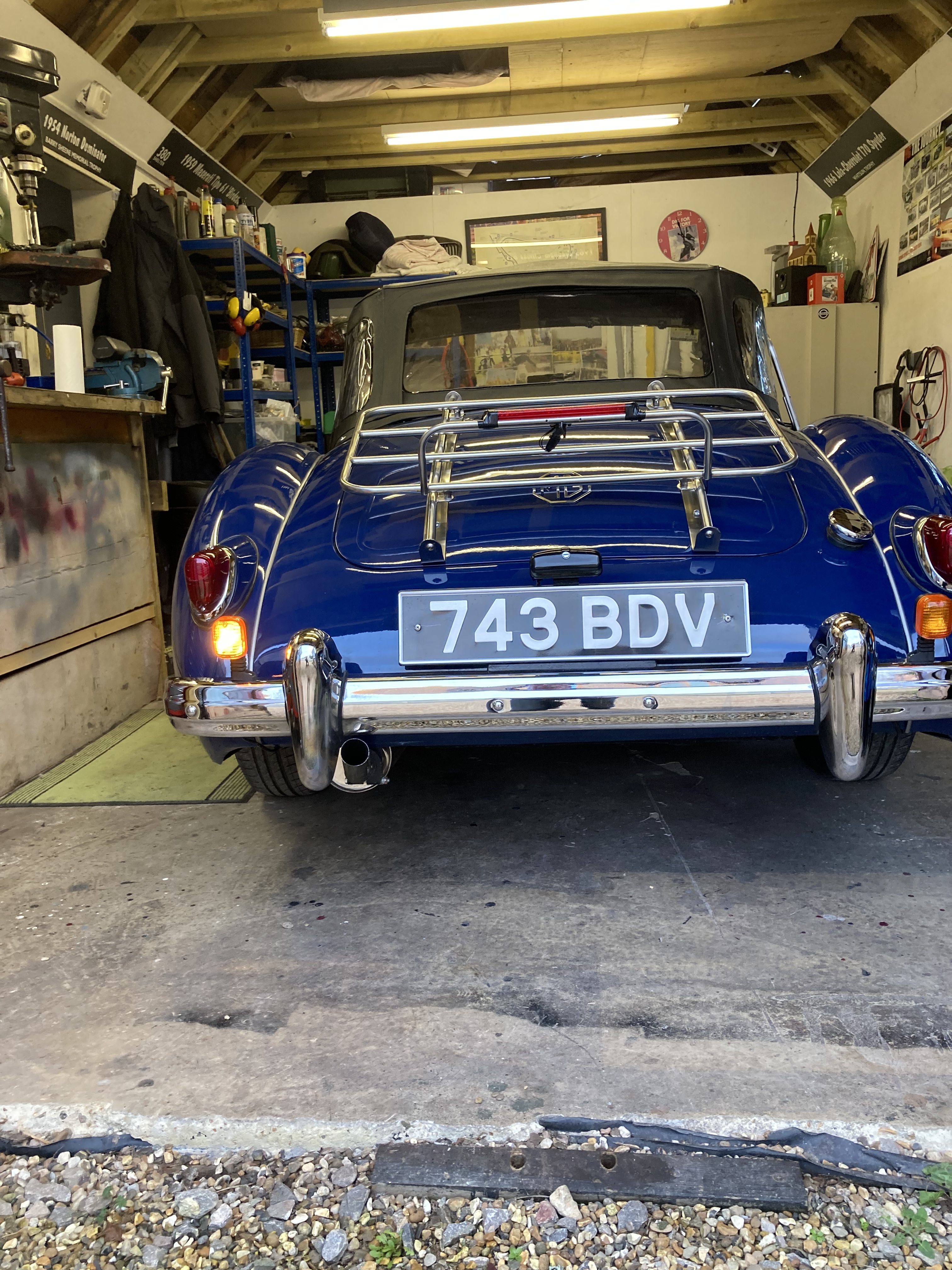
Rear Indicator Upgrade
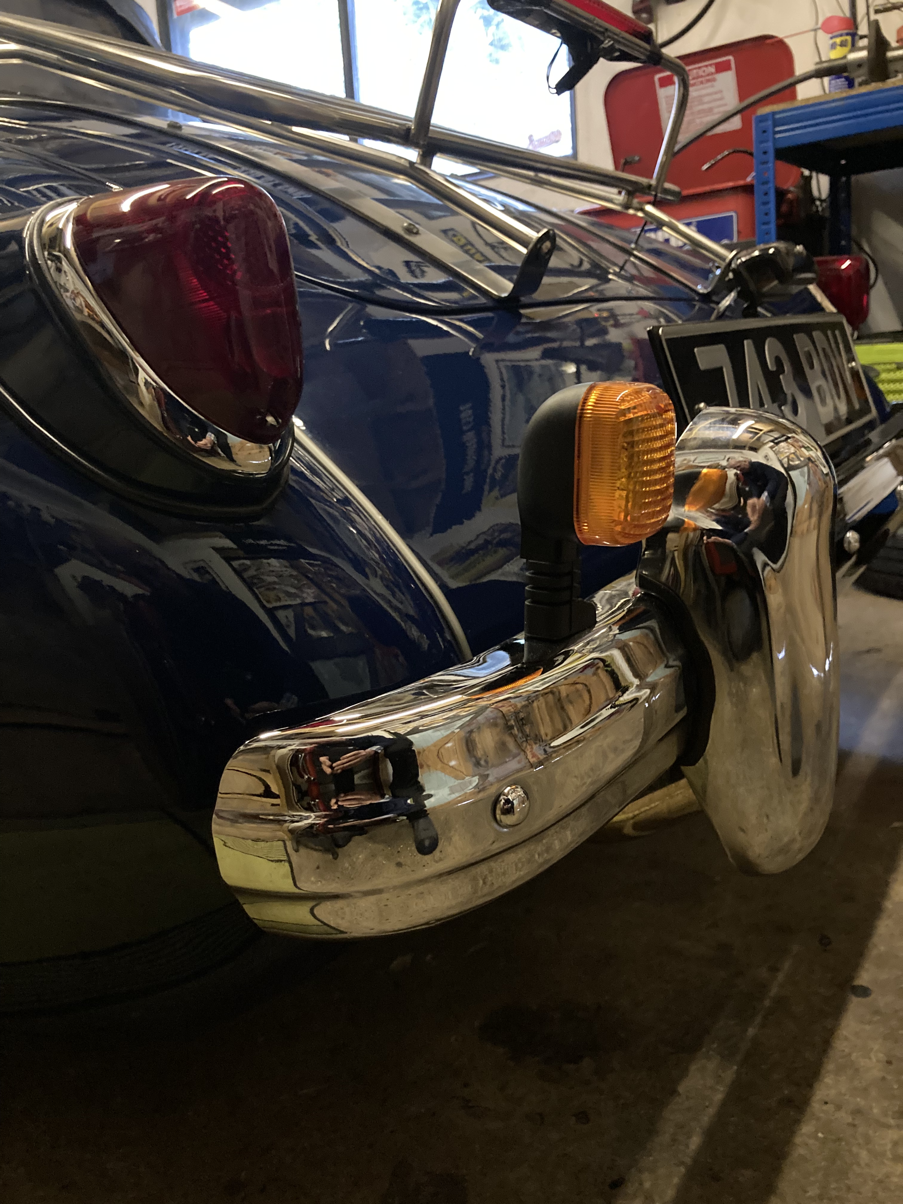
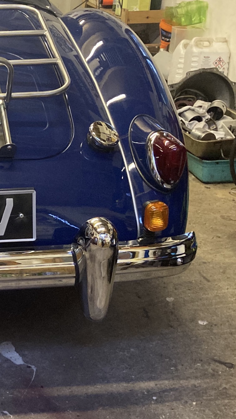
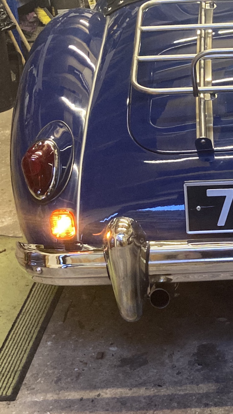
Having fitted the high level led brake light, which definitely improved following driver reaction, I was still very aware that modern drivers have no respect or understanding for a flashing red light for an indicator. I’ve had a couple of near rear end shunts and the odd shout of abuse. I’ve mused on the options for upgrading the indicators for a while now and decided I needed a winter job. I considered changing the 1500 lamp for the later 1600 plinth that has the same Lucas red lamp, but also a separate amber direction Indicator lamp above it. My problem with this solution was that it changes the pure lines of the 1500 in a material way. Also, the cost of a pair of 1600 plinths, due to their rarity, is excessive.
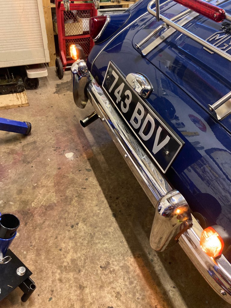
I wanted to avoid drilling the bodywork and for the fitment to be reversible, so my decision was to fit a pair of motorcycle sized lamps into the rear bumper.
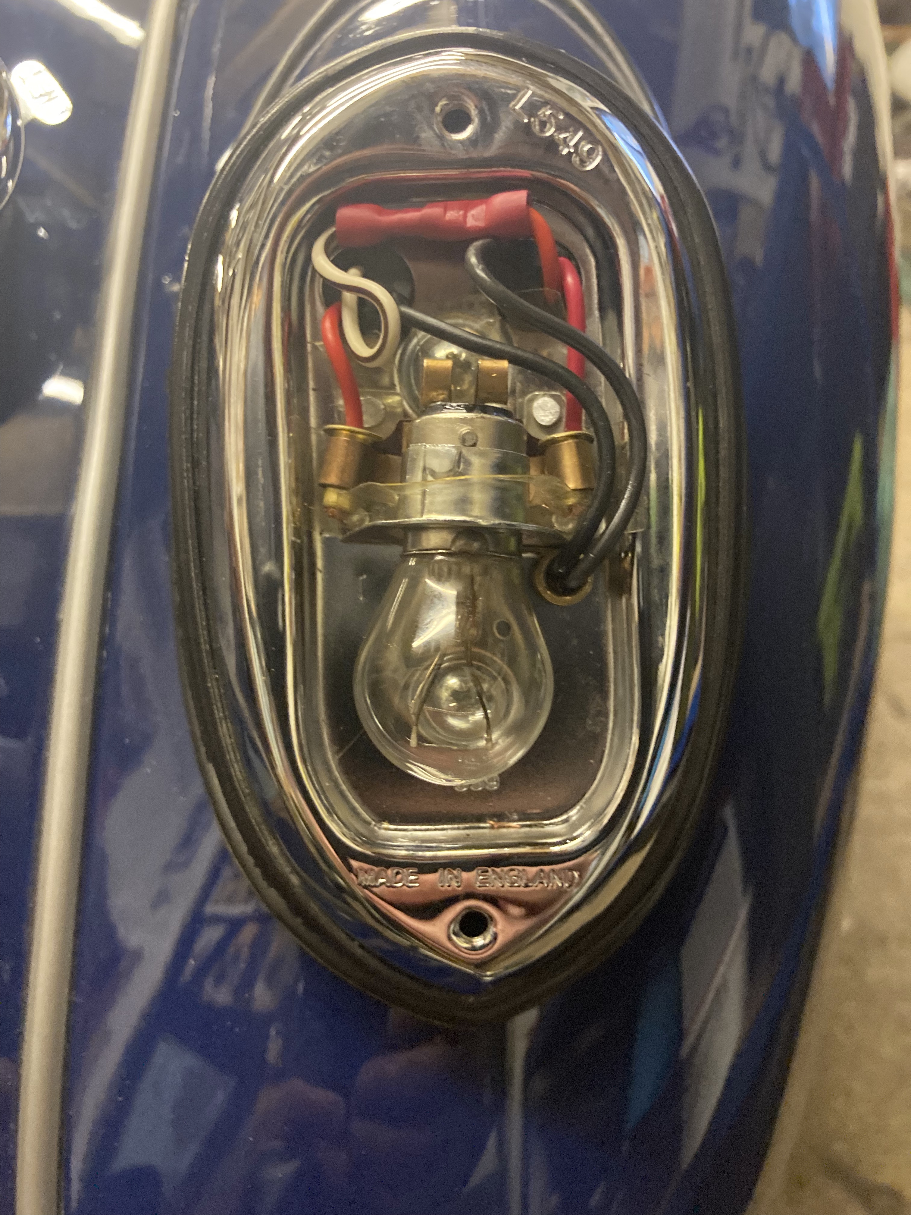
Wiring. The aim was to have only the amber flasher working and the red lamp purely for brake lights and sidelights. Because the 1500 had a shared brake light/flasher, enabled by the unique relay, the wiring needs to be changed. For full info on this, MGA Guru Barney, has every last detail on his site. Basically, it’s a case of separating the wiring from the flasher element of the rear light unit to feed the new single filament lamp and provide a new, separate feed wire from the brake switch to the two rear double filament brake lamps.
Finished wiring. The left red wire is the sidelight, the right red the new brake light feed. The white/blue wire is connected to the new lamps input cable, it’s red, as l only had red and black wire! The new black lead is the earth for the new lamp.
I already had a wire from the brake switch, following the loom along the chassis rail, to feed the 3rd brake light, but fitting one is easy. This wire then needs to split off using a three-way connector, to each brake light. This new wire is fed into the back of the lamp plinth into the lamp and connected up to the brake light terminal.
The indicator feed wires are white/blue for the left hand, white/brown for the right and these are disconnected from the lamp terminals and joined directly to the new amber lamp wires. That leaves the earth/ground cable from the new lamp, which l connected to the ground terminal in the old lamp. All my connections were made in the old lamp, so are nicely hidden when done.
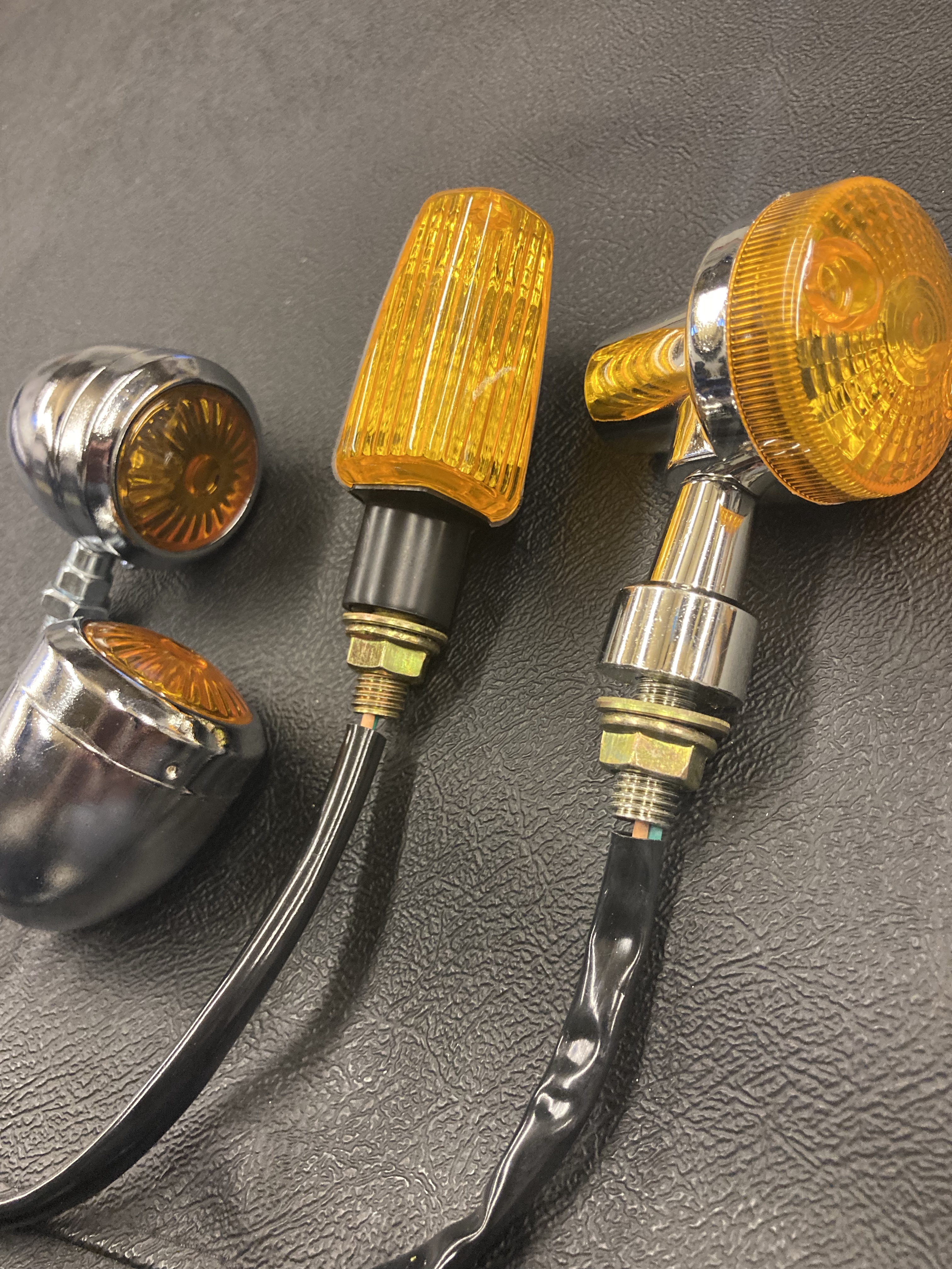
These were the other lights I bought but decided against.
This upgrade has been a great success, simple, low cost and very effective.
Hazard Warning Lights
Back in May 2023, l had the misfortune to breakdown with a seized engine on a difficult stretch of busy dual carriageway and without hazard warning lights. It was a scary experience and one not to be repeated, so I looked for a solution.
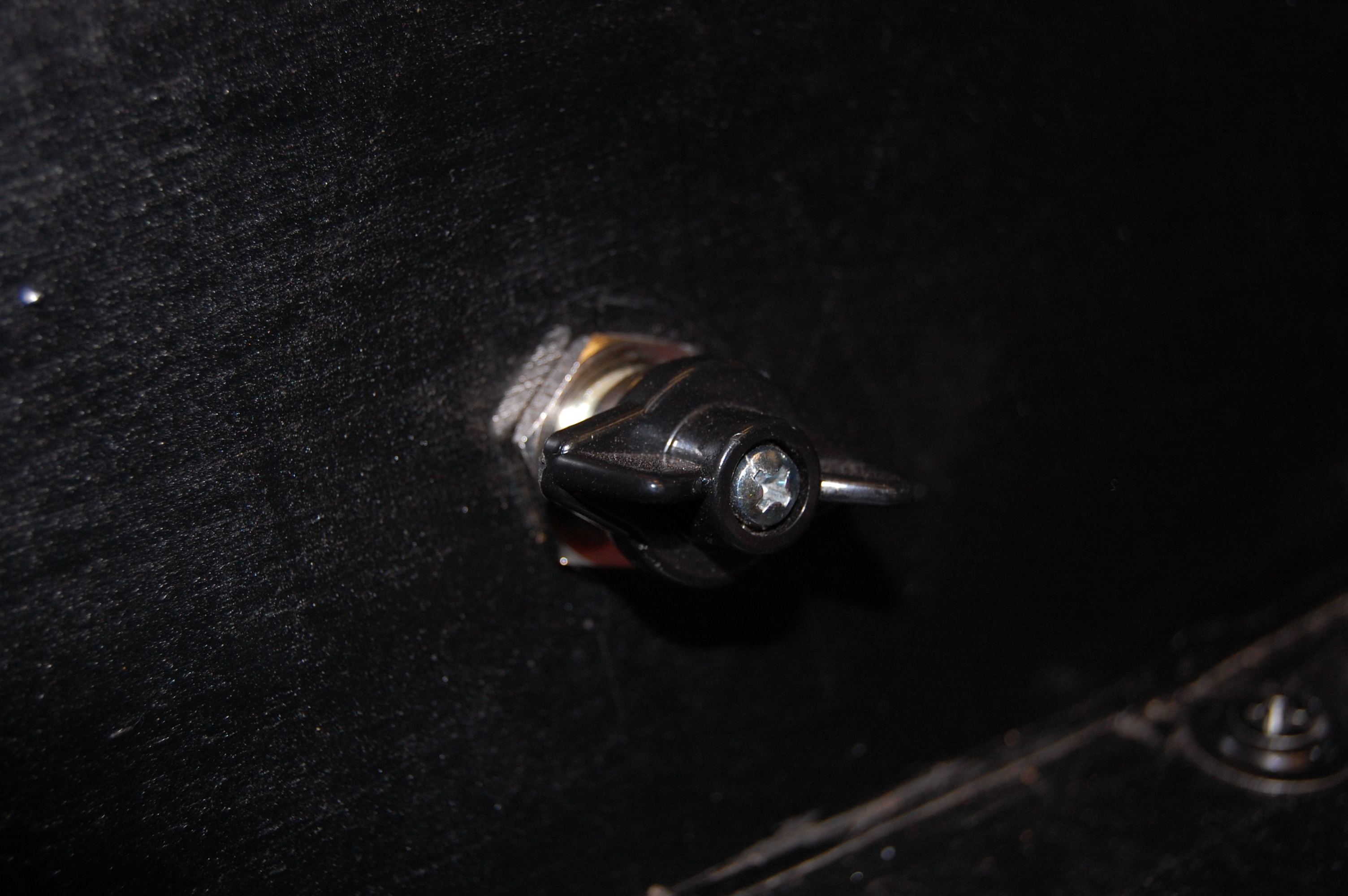
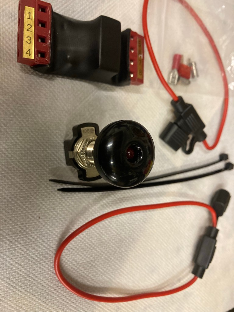
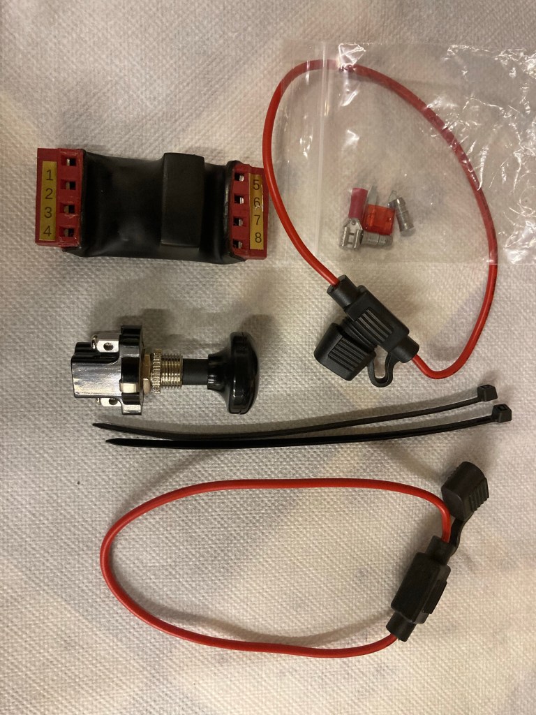
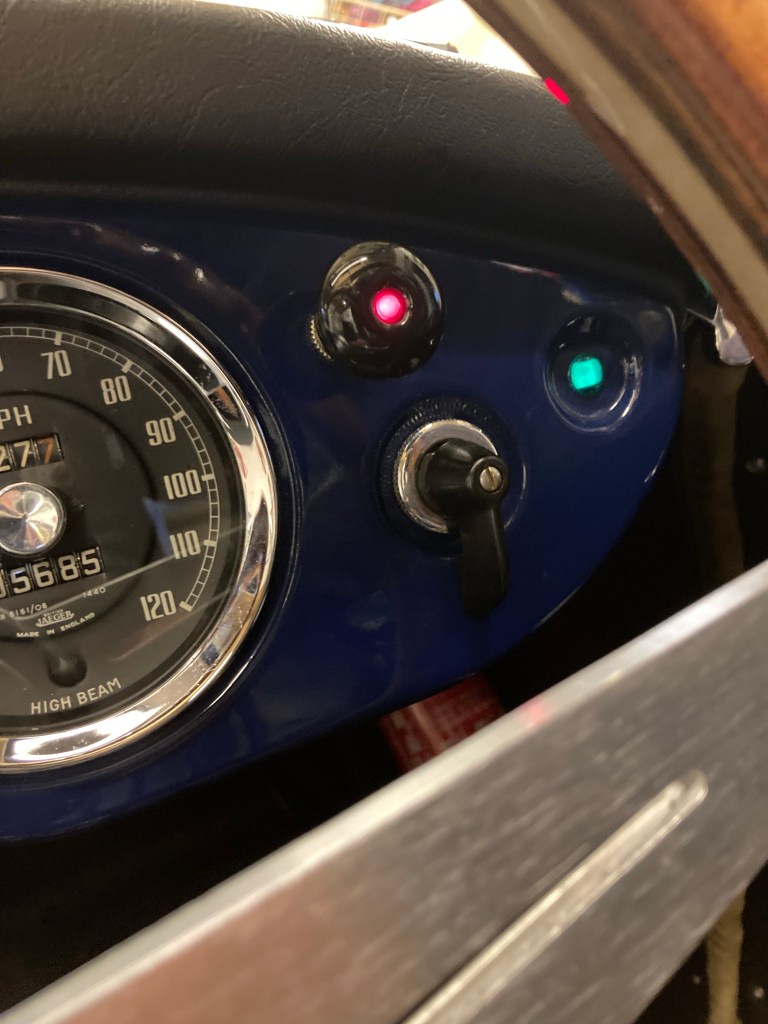
There are various kits out there, but the kit that I went with was from ‘Retronics’ at about £40. It’s aimed at classic vehicles and caters for vehicles fitted with the Lucas relay serving the single rear combined brake/indicator/sidelight set up. I also liked the black, domed switch with red flashing light, as it fits in discreetly with the other dash switches. It’s a relatively easy fit, but if help is needed, the two guys who run the business are extremely helpful.
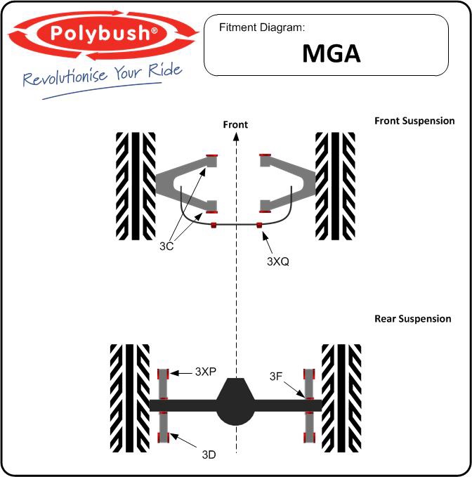
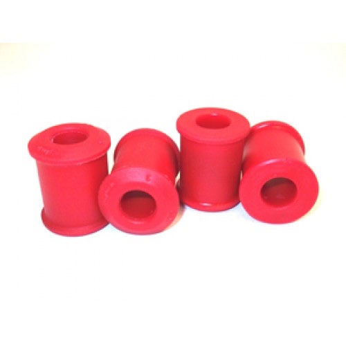
Polybush Suspension Bushes
During the restoration, I fitted MGB V8 bushes to the front lower wishbones, as the quality of the standard bushes was very poor, as were other rubber components. After 5,000 miles, the bushes started to deteriorate with an accompanying rattle over rough ground, so I decided to fit ‘Polybush’ blue ‘Comfort’ bushes.
The difference was noticeable, quieter and with crisp turn in. Next job could be rear spring hanger and anti roll bar upgrade.
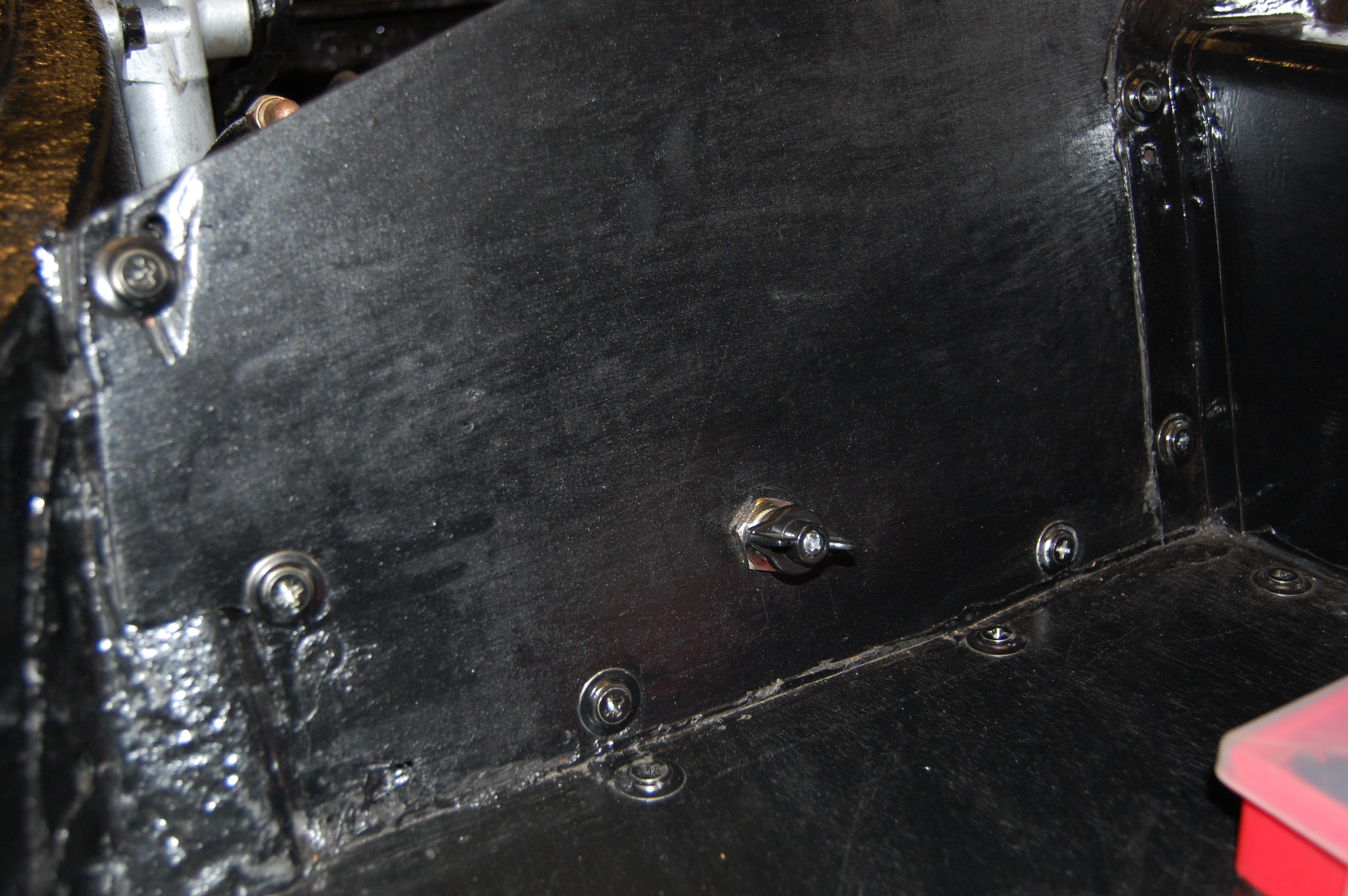
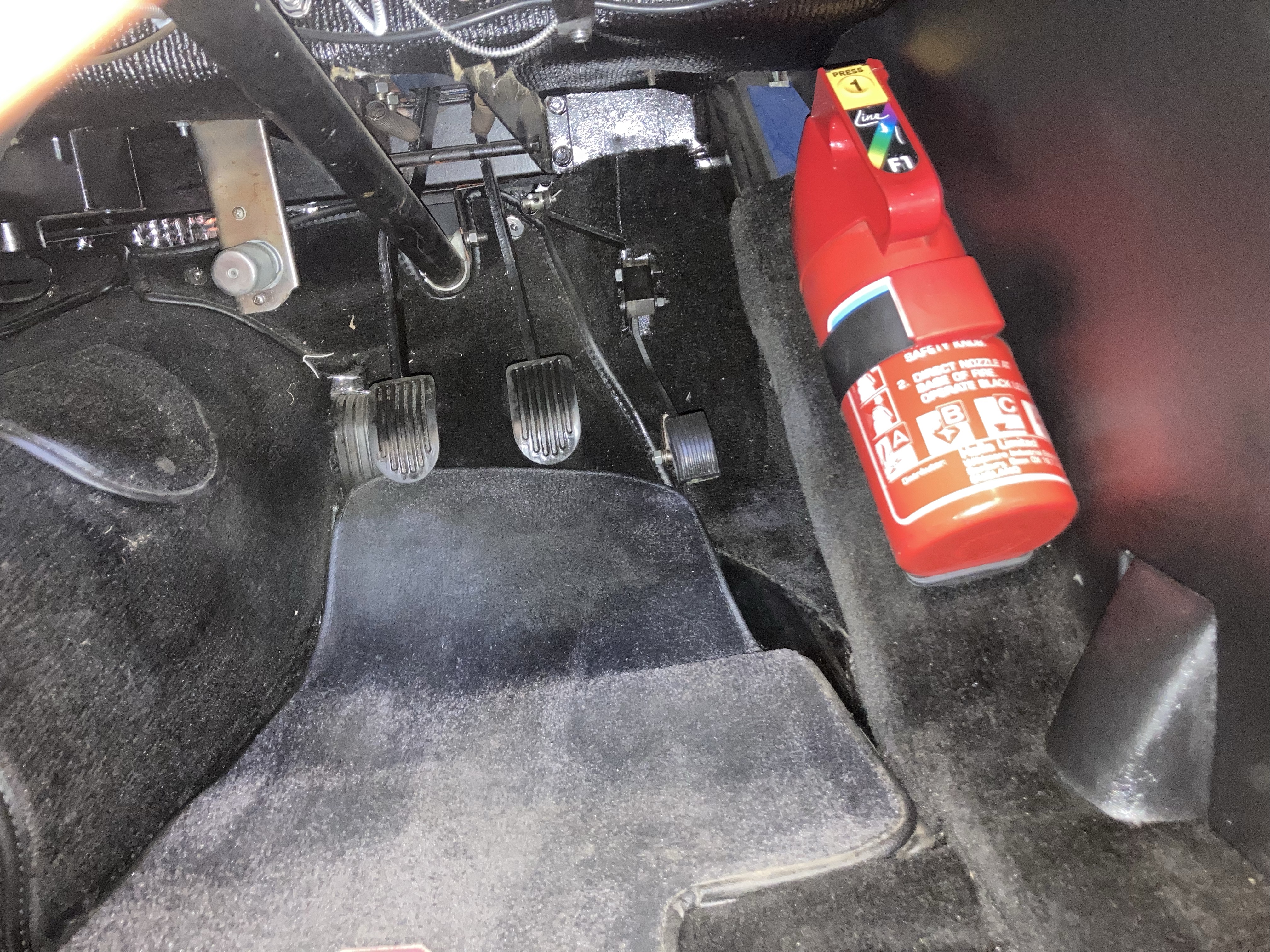
Fire Extinguisher
In an effort to keep the boot/trunk clear and also for speedier access, I’ve moved the powder extinguisher into the cockpit. Mounting is by two drilled holes in the angled chassis rail with self tapping screws through the plastic retaining strap.
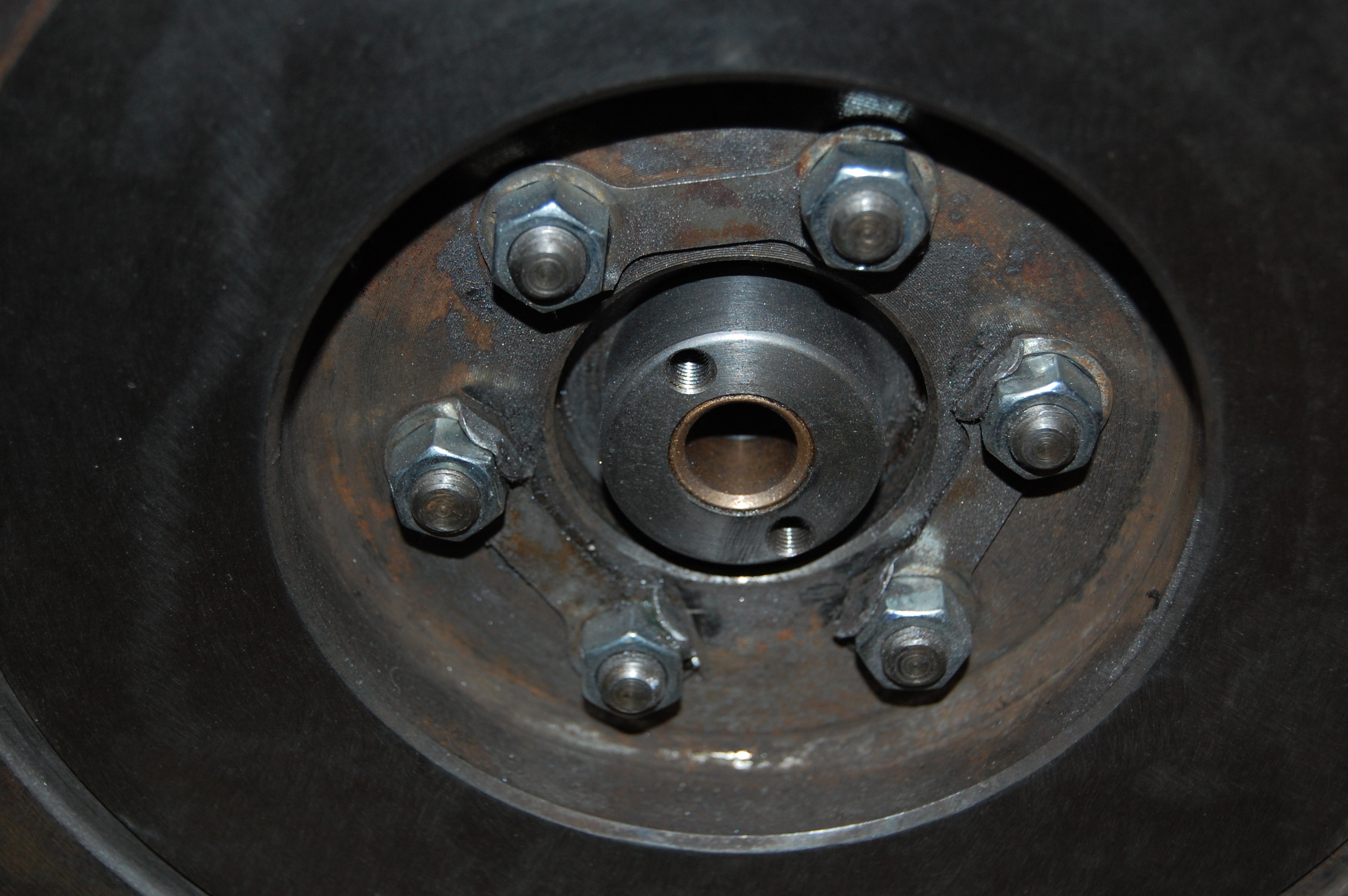
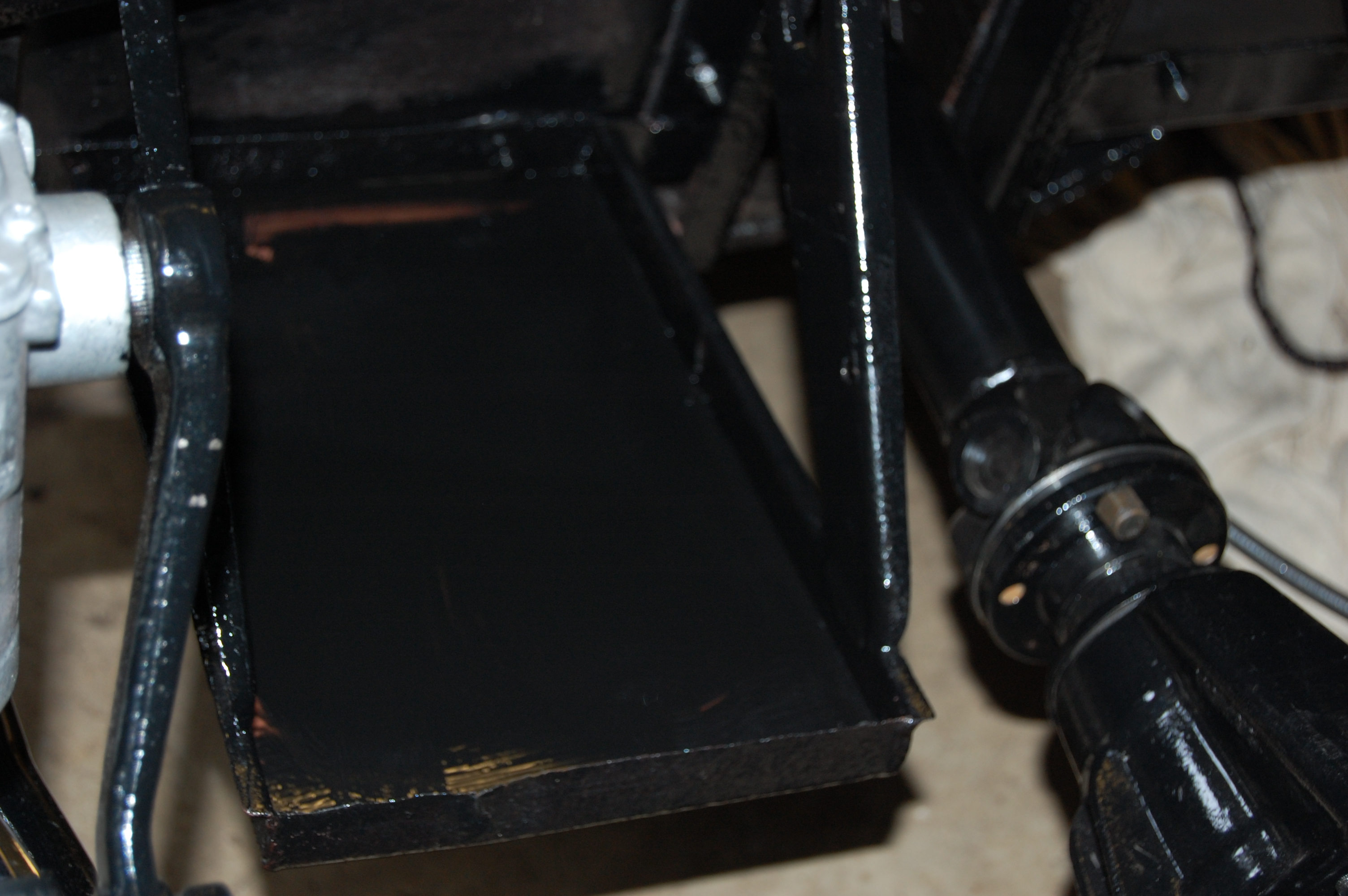
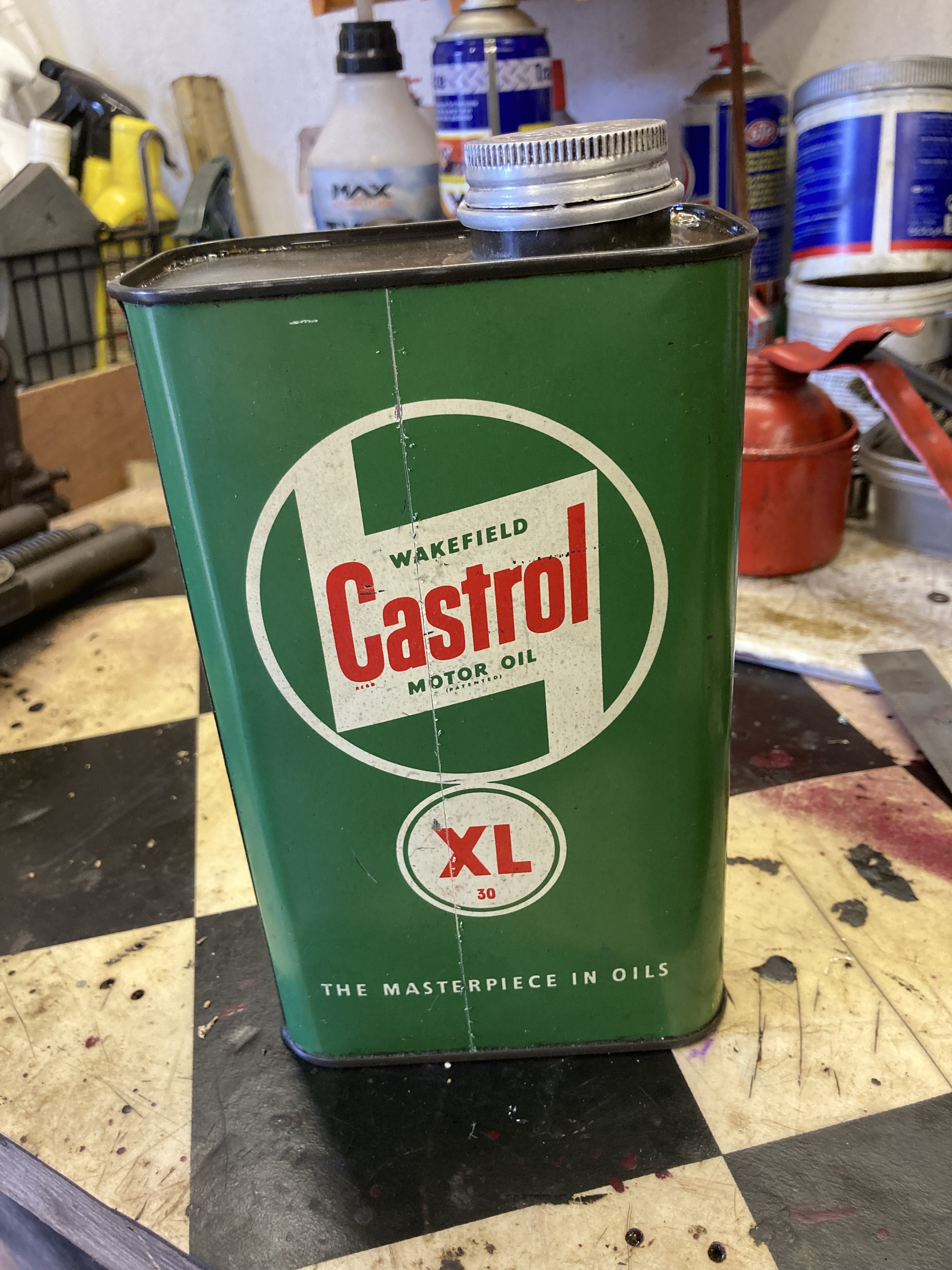
Rear Main Oil Drip Catcher
The nature of all BMC B Series engines including MGA and early 3 bearing MGB, is that they leak oil from the rear main crankshaft bearing. The reason for this is that there is no seal as such, but the oil is controlled by a scroll and thrower at the rear of the crankshaft. The volume of leakage is determined by the condition and fit of the scroll, journal and main bearing cap, which should all run to very close clearances. Any amount of wear or scoring will result in leakage. Often this is just an annoying drip on the garage floor, but in the worst cases it can be a catastrophic leak.
When at home, it’s enough to keep a tray or sheet of cardboard underneath to catch any drips, but it’s not so good when parked on a pristine drive.
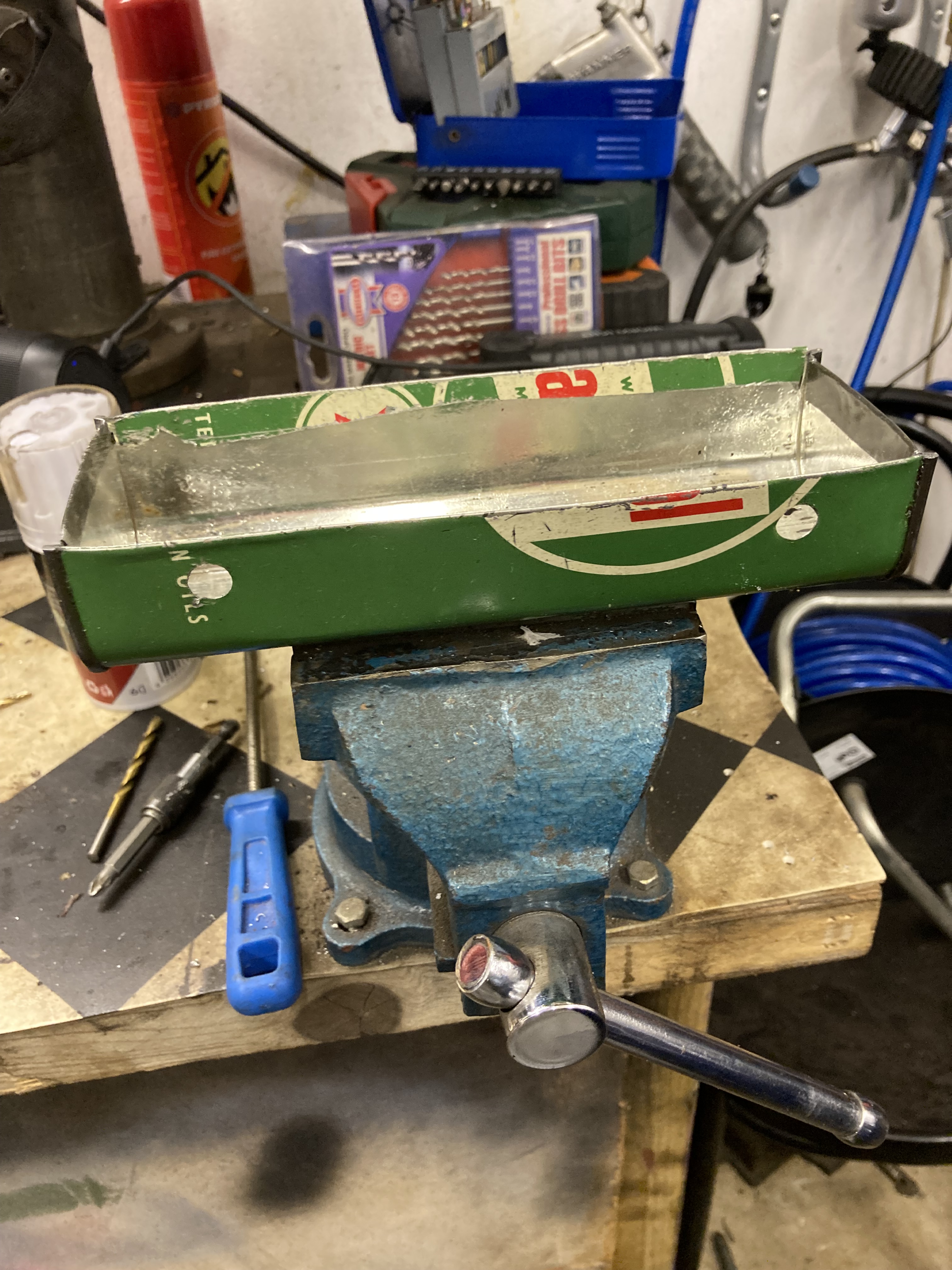
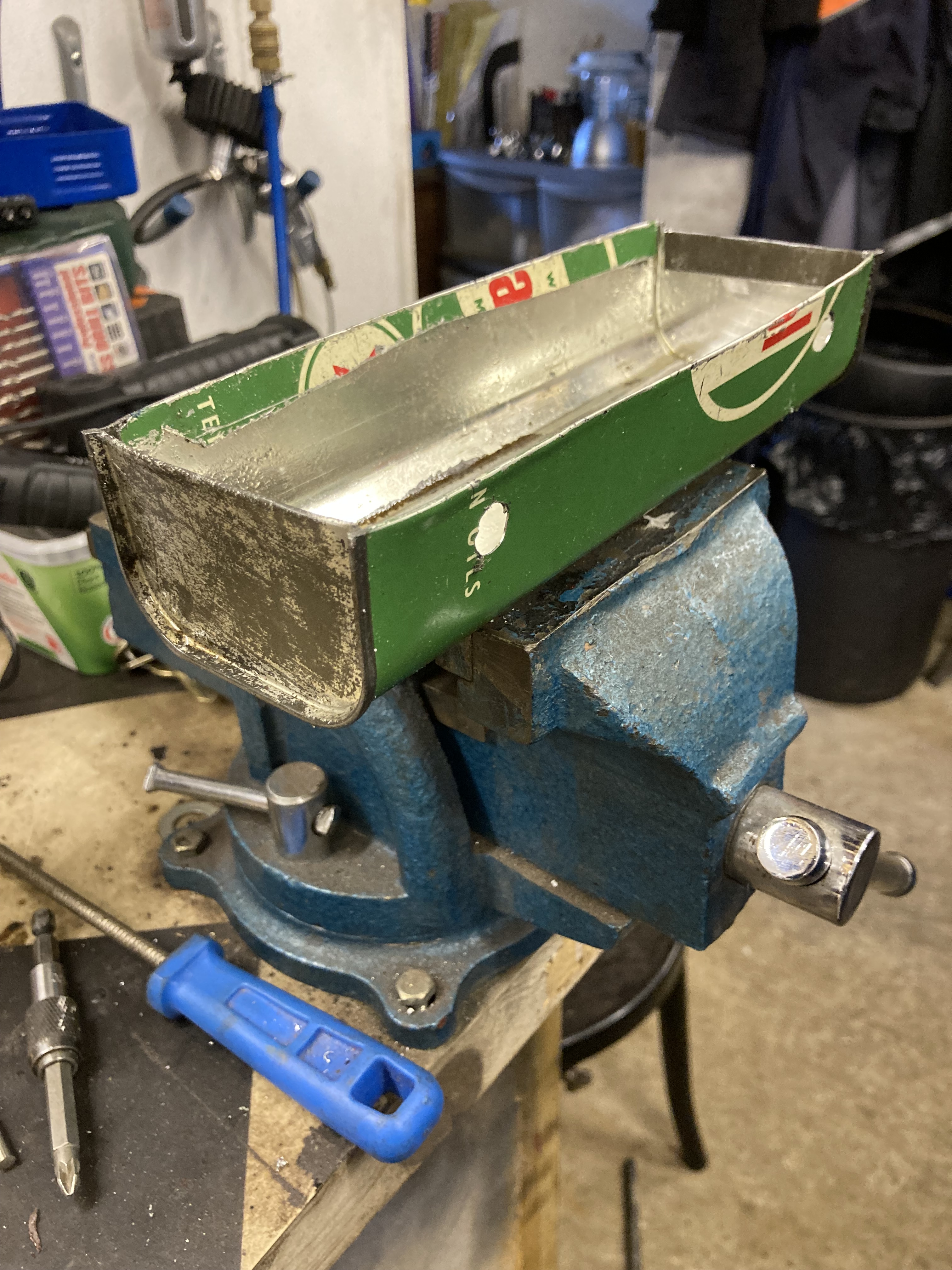
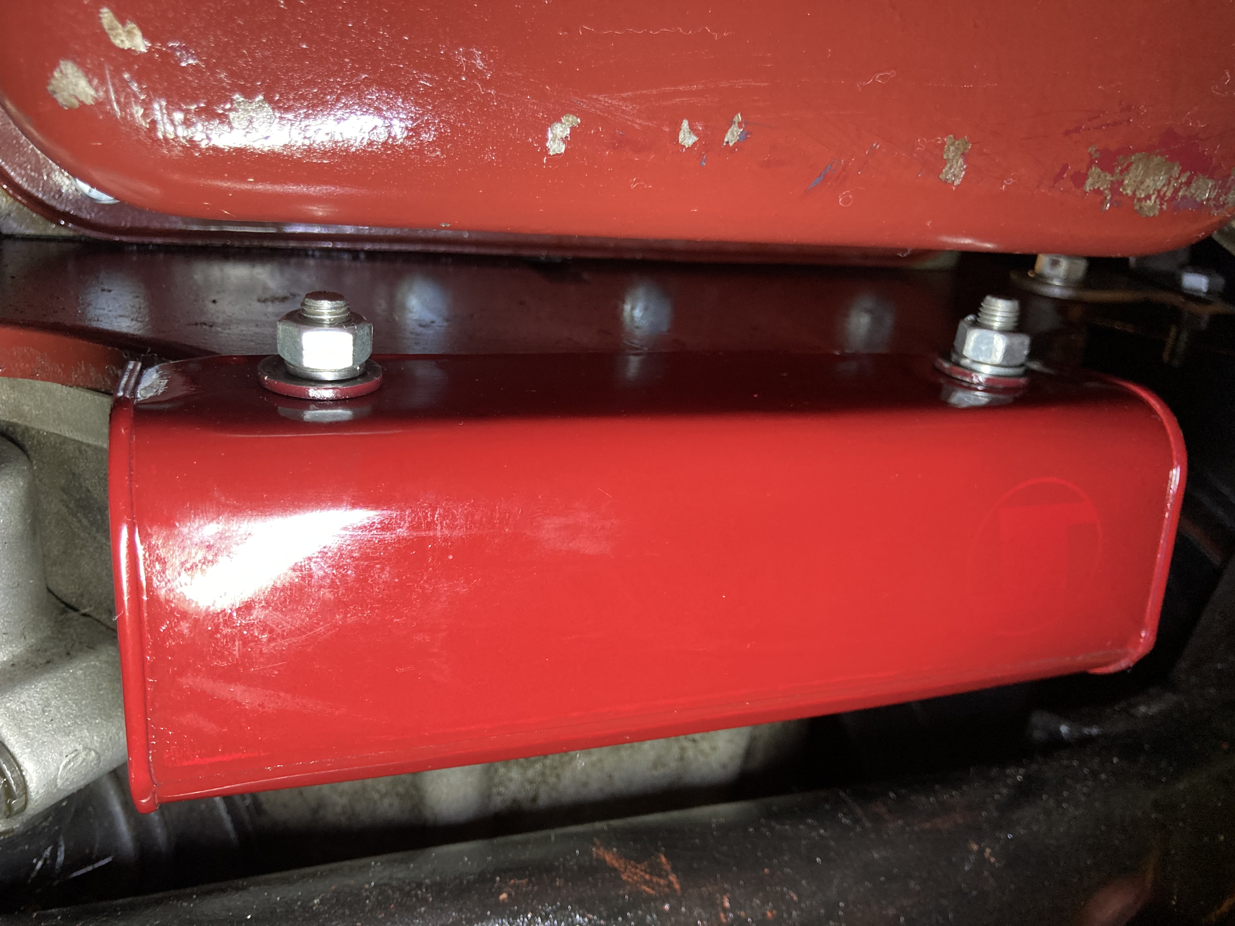
My new reconditioned ‘Skiptune’ engine is oil tight other than a small rear main leak, as is normal, nevertheless I decided to create a solution in the form of a drip catcher fixed to the back of the engine. There are many examples of home made versions, but they usually utilise the top section of a cut down gallon can, complete with cap and handle which both look obvious and hang down lower than the sump. I experimented with this idea, but wasn’t happy with the result. I happened to have an old quart Castrol can which is smaller and cut lengthways produced a perfectly sized tray that fitted more discreetly under the rear engine plate/gearbox join, where the oil drips out.
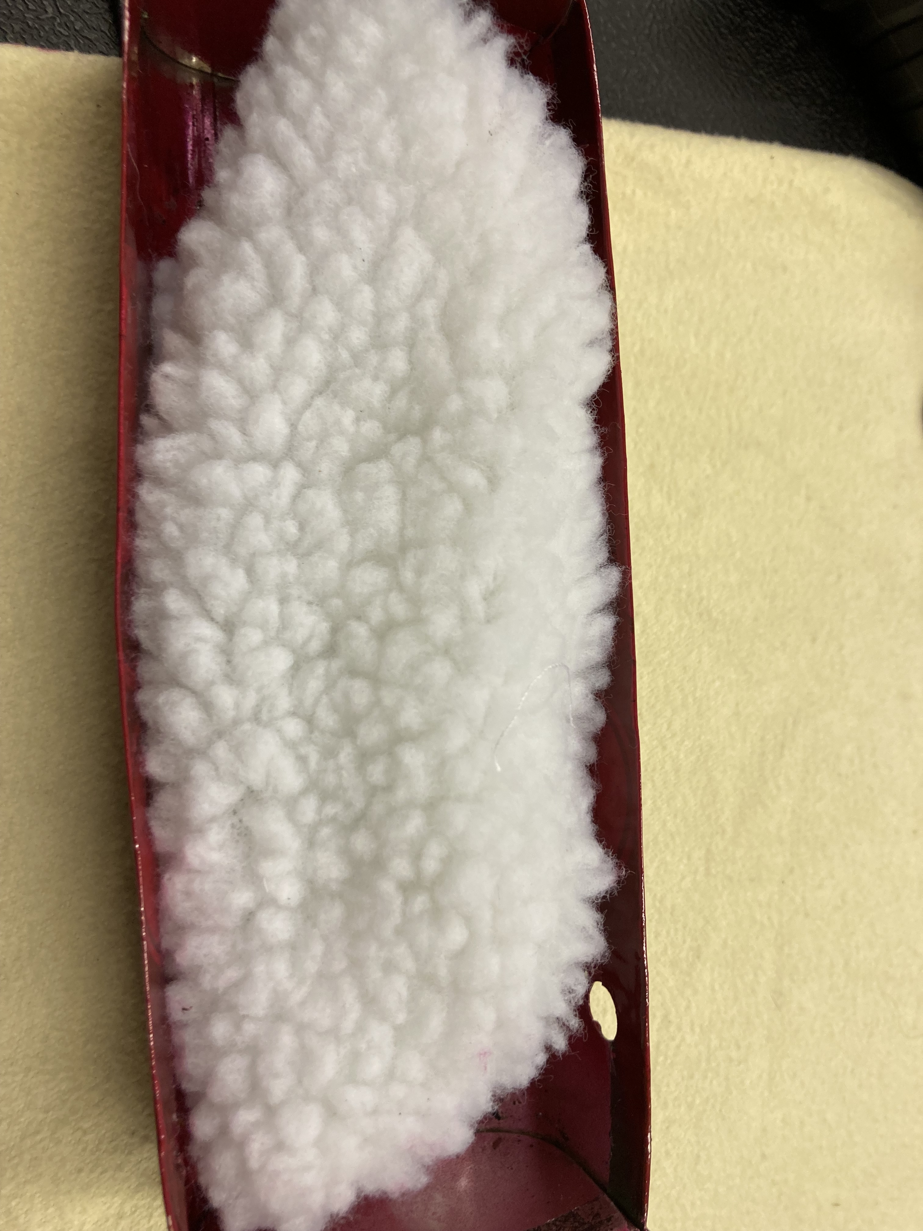
The tray is lined with absorbent material, which can be changed periodically.
No more embarrassing drips.


Hi Bill, like you, I’d like full inertial reel seatbelts to ferry around the grandkids. May I ask where you bought your belts, and what model you bought? I’d love to do something just like you’ve done. Thanks much! Cheers, Peter
Hi Peter,
Please accept my apologies, but somehow your message failed to register with me.
My seat belt installation has worked very well in practice, but off the top of my head, I can’t recall where I bought them.
I will however, check my invoices and let you know.
Thanks for your contact.
Bill.
The belts I used were Securon, which have the feature of being adjustable to allow for fitting at any angle. If I can find the model number, I’ll let you know.
I think they were the ones they market for MGB/Midget, which you’ll find on EBay. Bill.
Hi Bill, Thanks for the very informative discussion on the upgrades you have made to your car. I have recently started restoring my MGA which has been off the road for a number or years now. I have been contemplating a 5-speed gearbox conversion and was trying to work out whether to go for the T9 or Mazda MX5 option. The latter requires removal of the original gearbox mounts which I’m kind of reluctant to do. Your extensive photos makes understanding what is required for the T9 conversion a bit easier to follow and is probably the way I am leaning now. I also like your solution for the seatbelts. I had been contemplating what to do here and think your solution is what I will adopt when I get the that stage of the project.
I have just finished the welding repairs I needed to make to the chassis and before I painted it, needed to consider the gearbox (in case any alterations needed to be made and the seatbelts anchor points – as I was considering welding the nuts for the anchor points to the chassis. The car had seat belts in it when I got it which were just a lap sash belt and the anchor point was the wooden floor – I’m not sure how well that would hold in an accident.
Hi Anthony. Thank you for your kind comments and it’s great to hear that another restoration is about to start, with all it’s challenges, decisions and excitement.
With regards to the five speed gearbox upgrade, I can only say that after 4 years and 4000 miles, I’m still delighted with the T9 and love driving with it. I’m not really in a position to give a personal opinion on the Mazda conversion, as I’ve not driven one. One of the features I like about the T9 is that it feels very clunky (in a good way), like the original and with the remote shift, is a joy to use.
The seat belts have been a great success and work really well. Unfortunately, with any three point fixing set up in a roadster, you can’t avoid a bit of fiddling, when raising and lowering the roof. It’s easy enough though if you use a carabiner style catch at the chassis locating point.
My solution for mounting the reels, works well, but is fiddly with the body fitted and best to do before painting. I did mine after painting, which precluded welding plates on and led me to use stainless bolts/screws, which is fiddly and quite challenging.
Out of interest where are you located? What car do you have and how long have you owned it?
Please feel free to contact me at any point if you need any advice or encouragement. My email address is billnjeffries@gmail.com
Good luck
Bill.
Regarding your drip tray mod., am I correct in thinking that at least one end of the can has been removed making the tray more of a shelf to hold the oil absorbent wadding rather than an oil container? Am hoping to make one myself and have a suitable can ready. Roger Cooper
Roger
If you let me have your email address, I’ll send you all the photos of the tray. I don’t seem to be able to add photos here.
Bill.
Bill: thanks for the reply. My engine is currently in bits for full refurbishment with various “ nasties” having been revealed including wear to the rear crankshaft scroll but I had already felt that the oil leak needed attention as my son will keep the car in a garage which is integral to his house so we don’t want oil leaking out. I have already bought a stainless steel drip tray for the floor along with oil absorbent wadding. An attached drip tray plus, maybe, attention to the scroll “ seal” ought to help things. That garage sports insulated doors and the house HW tank plus associated plumbing so the MG may live a more luxurious life after handover.
My address is: reeacoop@ aol.com
BW, Roger